K23-SSI/USB/25B-C | OPERATING SOFTWARE OS6.0
44
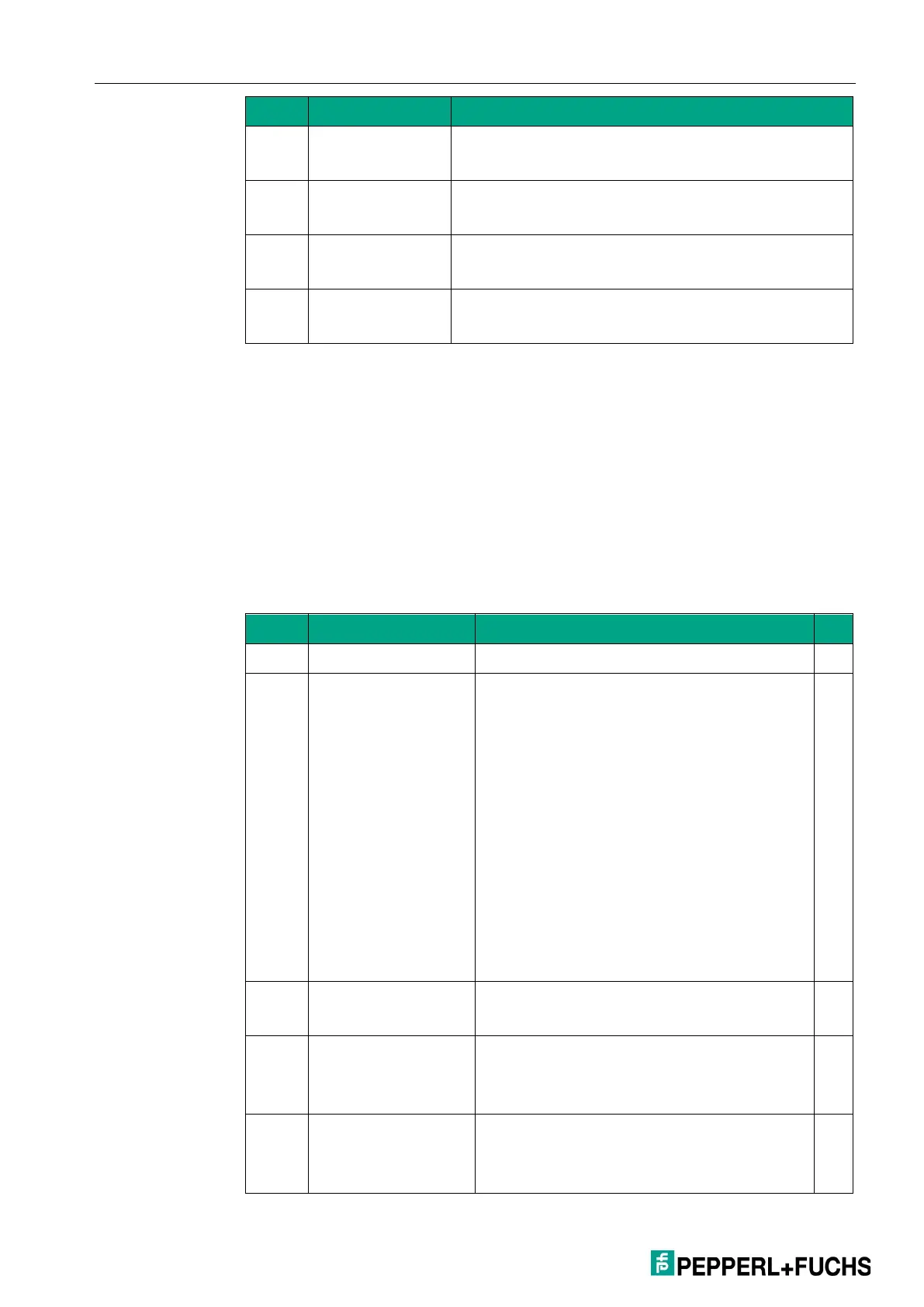
Pin 25 : Datastable output (Active High)
Pin 24: Error output (Active Low)
Pin 25 : Datastable output (Active Low)
Pin 24: Error output (Active High)
Pin 25 : Datastable output (Active Low)
Pin 24: Error output (Active Low)
/DATASTABLE
Pin 25 : Datastable output (Active High)
Pin 24: Datastable output (Active Low)
4.8 Command Menu
INPUT 1 ACTION (function input 1)
This parameter determines the control function of the input "Ctrl. In 1."
(s) = stat. switching characteristics (level modulation) INPUT CONFIG must be
set to ACTIVE LOW/HIGH.
(d) = dyn. switching characteristics (edge modulation) INPUT CONFIG must
be set to RISING/FALLING EDGE.
VALUE
Mode “SSI”: Transfer of the currently
detected position value (after bit
suppression and possibly performed
encoder zero offset shift) into the
parameter "SSI offset" (display offset)
Mode “Counter”: Reset / set of both
counter values (channel A and B) to the set
values in SET VALUE A u. B
Mode “Start/Stop”: Power-failure-proof
stored transfer of the current position or
angle measurement to the "Offset"
parameter.
(s)
Freezing of the current measurement
result / of the parallel output
POSITION
Mode “SSI”: Transfer of the current SSI
position to the "SSI-Zero" parameter
(s)
COUNTER A
Mode “Counter”: Reset / Set the counter
value of channel A to the set value in SET
(s)
 Loading...


