IVIS
®
Lumina XRMS Series III Hardware Manual Chapter 6 | Components and Specifications 42
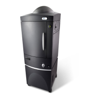
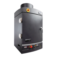
Imaging Chamber Features
Custom zero-background imaging chamber
Eight position optical filter emission wheel with seven filters (Table 6.2 on page 43)
22-position excitation filter wheel with 19 narrow band pass filters (see Table 6.2 on page 43 for
excitation filter specifications)
High-efficiency lens assembly
Sample illumination system
F/Stop control
Heated and regulated sample shelf temperature to reduce stress on an animal under anesthesia
Gas anesthesia manifold, including gas delivery and exhaust plumbing
Software-controlled field of view, F/Stop, focus, and optical filter wheels
Imaging Chamber Specifications
6.7 Optics
6.8 Optical Filter Wheel
A 22-position excitation filter wheel with 19 equally spaced narrow band filters is attached to the
back of the imaging chamber (Table 6.2). An 8-position, computer-controlled optical filter wheel is
located at the top of the imaging chamber in front of the imaging lens.
The filter wheel settings are selected in the Living Image software. See the Living Image
®
Software
Manual for IVIS Lumina XRMS Series III for instructions.
IVIS
®
Lumina XRMS Series III
Imaging Chamber
Description
Power requirements 4.0 A max at 120 V 2.0 A max at 240 V 50-60 Hz
Dimensions 19” x 28” x 39” 48 cm x 71 cm x 100 cm
Door opening dimensions 15” x 20.25” 38 cm x 51 cm
Weight 160 lbs 73 Kg
Optics Specification
Lens F/Stop f/.95- f/16
Field of View Fluorescence or bioluminescence mode: A (5cm
2
), B (7.5cm
2
), C (10cm
2
)
and D (12.5cm
2
)
X-ray mode: A, B, and C
 Loading...
