KENR9126 149
Troubleshooting Section
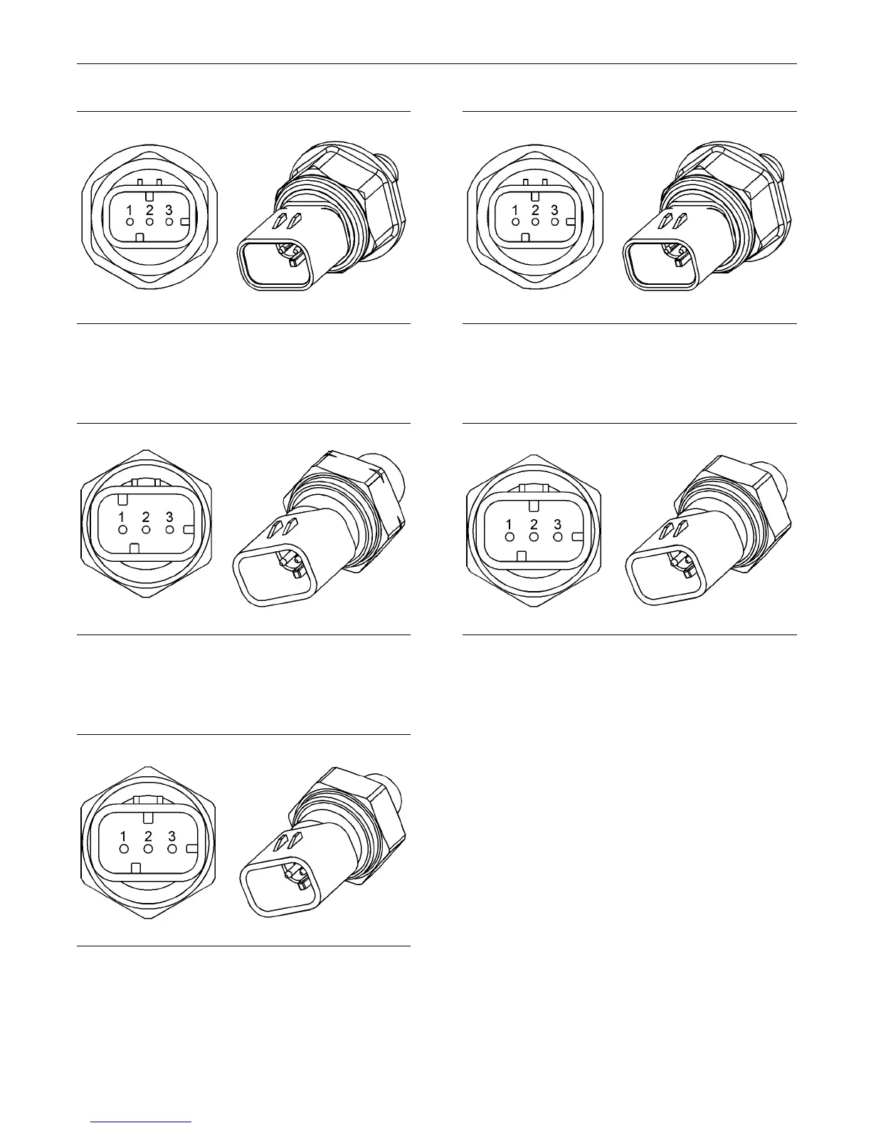
g01170309
Illustration 50
Fuel rail pres sure sensor
(1) Voltage supply (+5 VDC)
(2) Ground (GND)
(3) Signal (SIG)
g01170310
Illustration 51
Intake manifold pressure sensor
(1) Voltage Supply (+5 VDC)
(2) Ground (GND)
(3) Signal (SIG)
g01170311
Illustration 52
Typical example of the oil pres sure sensor
(1) Voltage Supply (+5 VDC)
(2) Ground (GND)
(3) Signal (SIG)
g01170309
Illustration 53
Typical ex ample of the fuel pressure sensor
(1) Voltage supply ( +5 VDC)
(2) Ground (GND)
(3) Signa l (SIG )
g01170311
Illustration 54
Typical example of the transmission oil pressure sen sor
(1) Voltage Supply (+5 VDC)
(2) Ground (GND)
(3) Signa l (SIG )
The troubleshooting procedures for the diagnostic
codes of each pressure sensor are identical. The
pressure sensors are active sensors. The pressure
sensor has three terminals. Active sensors require
supply voltage from the ECM. The ECM connector
P2/J2 supplies +5 VDC to terminal 1 of each
sensor. The common line is connected to each
sensor connector terminal 2. The signal voltage
from terminal 3 of each sensor is supplied to the
appropriate terminal at the ECM connector P2/J2.
Test Step 1. Verify All Active Diagnostic
Codes
A. T urn the keyswitch to the ON position. Wait at
least 10 seconds for activation of the diagnostic
codes.
B. Verify if any of the following diagnostic codes are
active:
 Loading...


