162 KENR9126
Troubleshooting Section
g01170313
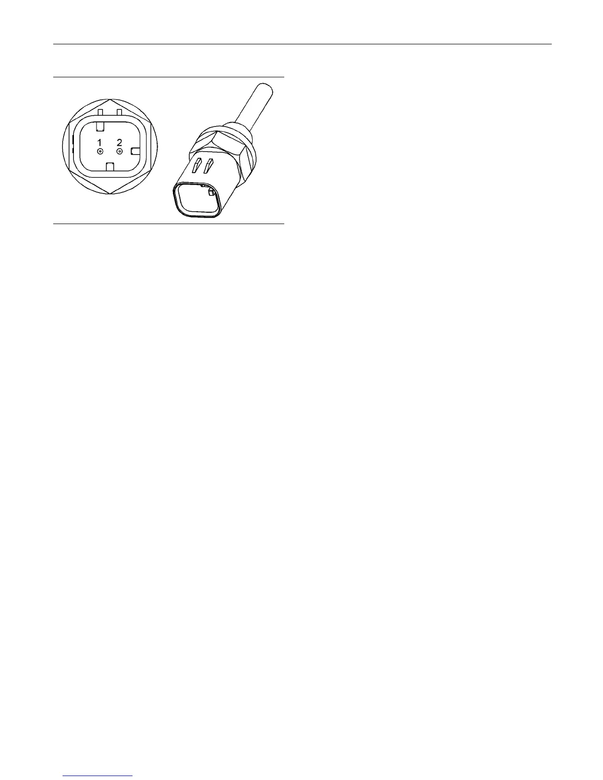
Illustration 61
Typical example of a temperature s ensor
(1) Signal (SIG)
(2) Ground (GND)
Test Step 1. Verify All Active Diagnostic
Codes
A. Connect the electronic service tool to the
diagnostic connector.
B. Turn the keyswitch to the ON position.
Note: Wait at least 30 seconds for activation of the
diagnostic codes.
C. Use the electronic service tool in order to verify if
any of the following diagnostic codes are active
or recently logged:
•
0110-03 Engine Coolant Temperature Sensor
voltage above normal
•
0110-04 Engine Coolant Temperature Sensor
voltage below normal
•
0174-03 Fuel Temperature Sensor voltage
above normal
•
0174-04 Fuel Temperature Sensor voltage
below normal
•
0177-03 Transmission Oil Temperature Sensor
voltage above normal
•
0177-04 Transmission Oil Temperature Sensor
voltage below normal
•
0172-03 Intake Manifold Air Temperature
Sensor voltage above normal
•
0172-04 Intake Manifold Air Temperature
Sensor voltage below normal
Expected Result:
One or more of the preceding diagnostic codes are
active or recently logged.
Results:
•
Yes – Proceed to Test Step 2.
•
No – The fault i
s intermittent. Proceed to Test Step
8.
Test Step 2. I
nspect Electrical Connectors
And Wiring
A. Thoroughly inspect ECM engine harness
connector P
2 and the suspect sensor connector.
Refer to Troubleshooting, “Electrical Connectors
- Inspect”.
B. Perform a 45 N (10 lb) pull test on each of the
wires in the sensor connector and the ECM
connector
that are associated with the active
diagnostic code.
C. Verify tha
t the latch tab of the connector is
correctly latched. Also verify that the latch tab of
the connector has returned to the fully latching
position
.
D. Check the screw for the ECM connector for the
correct
torque of 5.0 N·m (44 lb in).
E. Check the harness for abrasions and for pinch
points f
rom the sensor to the ECM.
Expected Result:
All connectors, pins, and sockets should be
completely coupled and/or inserted. The harness
shoul
d be free of corrosion, abrasion, and pinch
points.
Resul
ts:
•
OK – Proceed t o Test Step 3.
•
Not OK – Repair the connectors or the harness
and/or replace the connectors or the harness.
Ensu
re that all of the seals are correctly in place
and ensure that the connectors are completely
coupled. Clear all inactive diagnostic codes. Verify
that
the repair has eliminated the fault. Proceed to
Test Step 3 if the fault has not been eliminated.
Tes
t Step 3. Verify That The Diagnostic
Co
de Is Still Active
A. Turn the keyswitch to the ON position.
Note: Wait at least 10 seconds for activation of the
diagnostic codes.
B. Access the “Active Diagnostic Code” screen on
the electronic service tool and check for active
d
iagnostic codes.