Adjustment
11 - 55
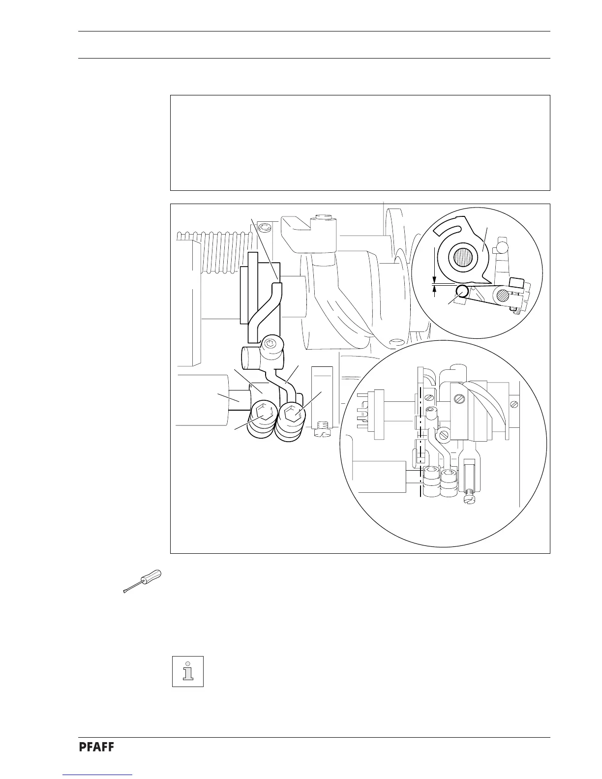
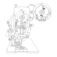
11.07.09 Cutter control lever for the control cam of the cutter
Requirements
At the left point of reversal of the rock shaft 3
1. the cylinder of control lever 4 and of reversing lever 5 must be positioned at the centre
of the control cam 6;
2. between the cylinder of control lever 4 and the outer diameter of the control cam 6
there must be a distance of 0.3 mm.
6
5
2
4
3
1
0.3 mm
6
4
Fig. 11 - 51
● Bring needle bar to BDC and operate engaging lever by hand.
● Loosen screws 1 and 2.
● Turn balance wheel in turning direction, until rock shaft 3 is in its left point of reversal.
● Adjust control lever 4 and reverse lever 5 according to requirement 1.
● Turn control lever 4 according to requirement 2.
● In this position and taking requirement 1 into consideration, tighten screw 1.
Screw 2 remains loosened for later adjustments.