39
14 Stromlaufpläne
Circuit diagram
2 Circuit diagrams
2
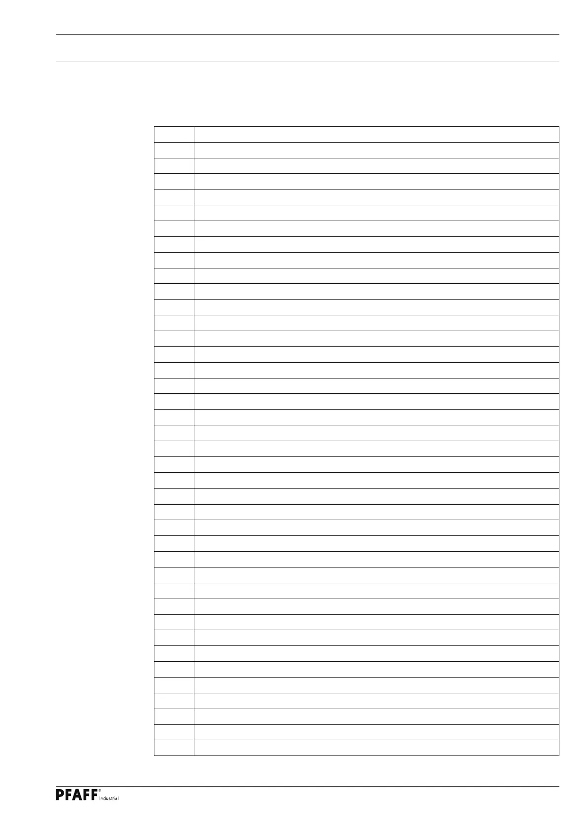
.01 Reference list for the Circuit diagrams 91-191 501-95
A1 Control unit P40 ED
A2 Control panel BDF S3
A14 Sewing head recognition system (OTE)
H1 Sewing lamp (optional)
H10 LED stitch counter
M1 Sewing motor
Q1 Main switch
S1 Manual backtacking key
S1.1 Pedal speed control unit
S6 Start inhibitor (E6 stop)
X0 PC-interface (RS 232)
X1 Motor
X2 Incremental transducer
X2.1 Incremental transmitter adapter
X2.2 Synchronizer adapter
X2.3 Y5-911/.. backtacking device
X3 Speed control unit
X3.1 Y2 thread trimmer -900/..
X4 A2 Control panel BDF S3
X4.1 Y4 automatic foot lift ( -910/.. )
X5 Out-/input
X5.1 S1 Manual backtacking key
X6 Bobbin thread monitor (optional)
X7 Photoelectric barrier (optional)
X8 Y8 thread tension release (FSL)
X22 Y2 thread trimmer -900/..
X24 Y4 automatic foot lift ( -910/.. )
X25 Y5 backtacking device ( -911/.. )
X28 Y8 thread tension release (FSL)
X50 A14 Sewing head recognition system (OTE)
Y2 thread trimmer -900/.
Y4 automatic foot lift ( -910/.. )
Y5 backtacking device ( -911/.. )
Y8 thread tension release (FSL)