10
3.11. Connecting the RS-485 Interface
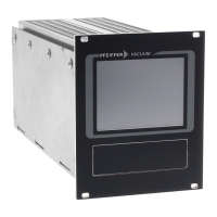
Interfacing is provided by means of an RJ45 plug (modular
plug) at the socket “RS-485” on the rear of the unit.
Physical Connection
“RS-485” pinout
A RS-485 bus is arranged as depicted in
the figure below, for example. By means
of standard modular connectors, cables
and branch-offs the signals are looped
through from one unit to the next.
Connection to a fixed bus system
➡ Connect all units with D+ (pin 5) and D- (pin7) to the bus.
The bus must be terminated at both ends with RT.
Networking of several units
➡ Loop the bus through with the aid of a tee piece.
The bus must be terminated at both ends with RT.
All units connected to the bus must be set to a different inter-
face address [P:797].
Only extra-low voltages may be connected to
the RS-485 interface.
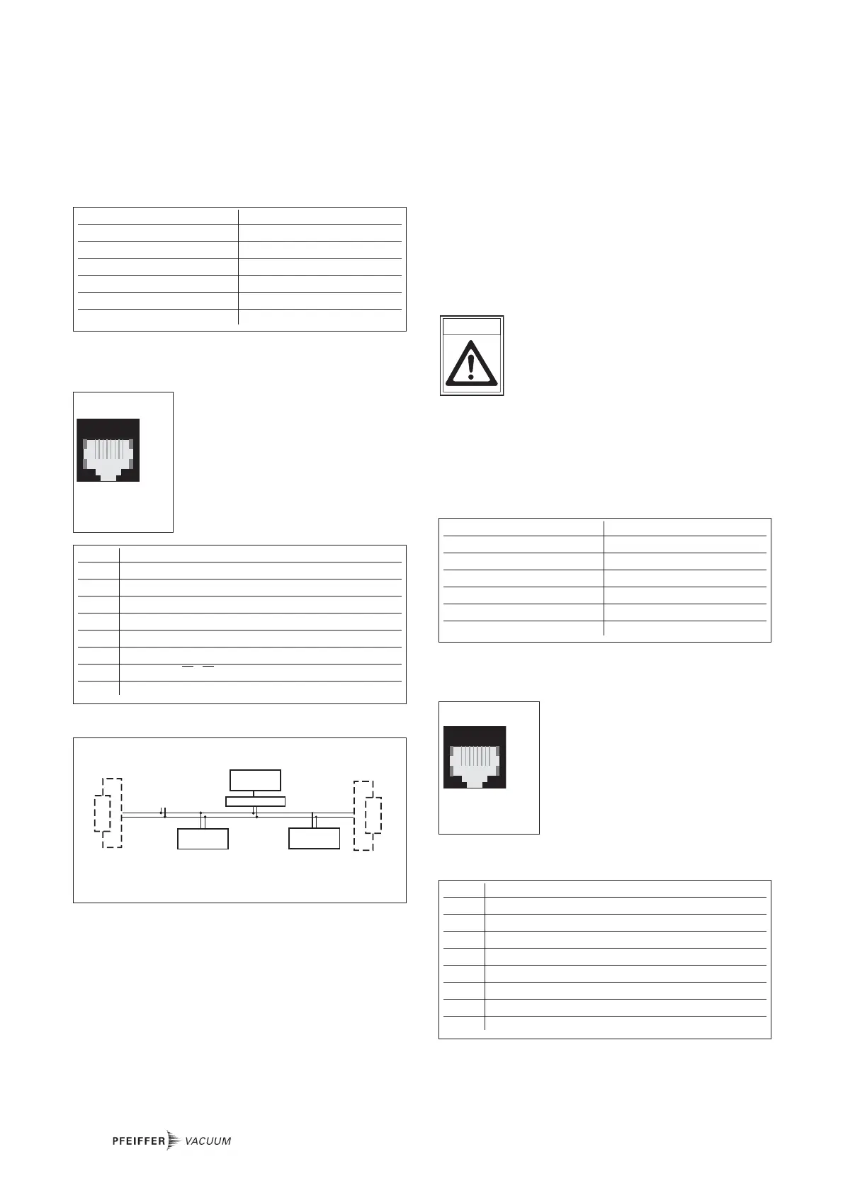
3.12. Connecting the RS-232 Interface
Interfacing is provided by means of an RJ45 plug (modular
plug) at the socket “SERVICE” on the rear of the unit.
Physical Connection
“Service” pinout
1)
Caution! No connections may be run to these pins. They
are only used by PFEIFFER VACUUM Service!
 Loading...