6
3.1. Before Installing the Unit
Never convert or modify the unit on your own.
The unit must be installed in a suitable case in
line with the ambient conditions encountered
(see Chapter 10 “Specifications”).
Electrical wiring diagram: see Chapter 11.
➡ During all installation work make sure that the mains plug
has been disconnected and that it is not reconnected inad-
vertently.
3.2. Ambient Conditions
➡ Install the TCP 3000 unit while maintaining the following
ambient conditions:
LLooccaattiioonn
: weather protected (indoor).
TTeemmppeerraattuurree
: +5 °C to +40 °C.
RReell.. hhuummiiddiittyy ooff tthhee aaiirr::
80 % at T ≤ 31 °C
up to 50 % at T ≤ 40 °C
AAttmmoosspphheerriicc pprreessssuurree::
86 kPa to 106 kPa
IInnssttaallllaattiioonn hheeiig
ghhtt
: 2000 m max.
PPoolllluuttiioonn lleevveell::
2
EExxcceessss vvoollttaaggee ccllaassss::
II
CCoonnnneeccttiioonn vvoollttaaggee::
1-phase/L1-N ~ 230-240 V (± 10 %), 50/60 Hz
3-phase/Lx-Lx 3~ 208-240 V (± 10 %), 50/60 Hz
3.3. Rack Mounting
To install the unit in a 19-in. rack enclosure, insert the unit as
required into a 19-in. 3 HU mounting frame and then affix the
mounting frame.
The ambient temperature within the rack must not exceed
+40 °C.
The unit must be installed in an enclosure which complies
with the required type of protection in each case.
Cooling/Air Circulation
The drive electronics of the TCP 3000 generates heat at an
amount equivalent. To dissipate this heat, you must ensure
that air can circulate freely around the unit.
WARNING
3.4. Mains Connection
The electrical connection must be carried out by
an electrician (electrical instructed person) and
in accordance with local regulations. Voltage
and frequency values on the TCP 3000 rating
plate must concur with mains voltage and mains
frequency values.
➡ The wire cross-section must be rated according to the
locally applicable regulations in consideration of the
currents given in the following chapter.
➡ Provide an electrical disconnecting facility on the device
side (see Chapter. 3.5.).
The protective ground function is provided through the mains
plug. An additional ground connection via the bolt on the rear
of the equipment is recommended.
SSiinnggllee pphhaassee ooppeerraattiioonn::
A factory setting protects the mains connector
and the internal cable for overloading.
TThhrreeee pphhaasseess ooppeerraattiioonn::
cancel the overload
protection with
[[PP::002299]]
(please refer to section
5.2.).
Connection: 4 pole cable plug (article no. please
refer to spare parts)
Identification: Phases: L1, L2, L3 (black) and
protective earth; PE (yellow/green)
– Cable socket for power supply connection is included in
the delivery.
☞
PLEASE NOTE
3. Installation
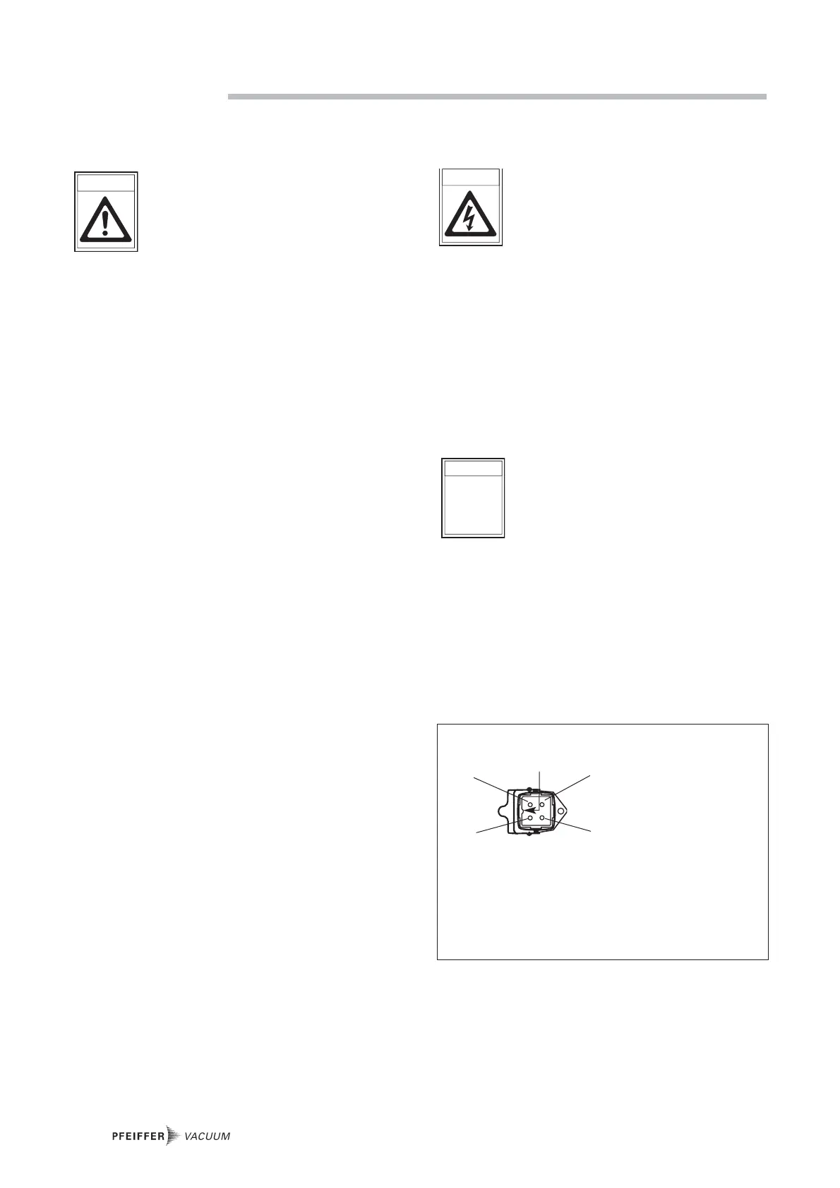
3 phase,
220088 VV 33~~ ((++2200//--1100 %%))
1 Mains connection, phase L1
2 Mains connection, phase L2
3 Mains connection, phase L3
4 PE (protective earth)
1 phase,
223300 VV~~ ((±± 1100 %%))
01 Neutral line
02 Mains connection, phase L1
03 not connected
04 PE (protective earth)
Pin configuration mains connection (Power supply)
01
04
02
03
Code

 Loading...