7
3.5. Constructional Protection
For the equipment, a disconnecting facility needs to be provi-
ded on the device side by way of either a switch or a power
switch. This facility must fulfil the following conditions:
- Location in the vicinity of the equipment or easy to reach
by the operator.
- The disconnecting facility must be marked as such for the
specific equipment.
The disconnecting facility on the device side
and also the possibly used power switch must
be selected in consideration of the locally
applicable regulations and the currents stated
in the following:
SSiinnggllee--pphhaassee ooppeerraattiioonn::
nominal current 14.7 A;
overload current 22 A
33--pphhaassee ooppeerraattiioonn::
nominal current 10.5 A; no
overload margin is allowed.
➡ Install constructional protection fuse.
3.6. Connecting the Pump
➡ Connect the pump using the connecting cable (52) to the
socket marked PUMP on the TCP 3000.
➡ Lock the bayonet catch (51, 53) after plugging in. After
locking both seals must be secured with the delivered set
screws.
At the open electrical connection or at the
disconnected pump cable on unit side, you
must expect dangerous voltages while the
pump is still running.
Risk of suffering an electric shock when
touching the contacts.
WARNING
CAUTION
To connect the pump only use connecting cables from
PFEIFFER-VACUUM.
Connect or disconnect the connector at the
drive electronics only after the pump has
stopped completely and after the unit has been
disconnected from the mains power.
3.7. Connecting the Vent Valve (only Turbo
Pump)
The vent valve (accessory) is used to vent the pump when
shutting the pump down or in the event of a power failure.
The vent mode is selectable through the front panel controls
or the RS-485 interface.
➡ Install the vent valve at the turbopump in accordance with
the operating instructions (see “Supplementary Informati-
on, Chapter 13”).
➡ Connect the control cable of the vent valve to the control
cable “Vent” X8 of the pump cable.
CAUTION
50 51 52 X7X2
X8
53
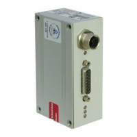
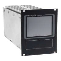
Connecting the turbopump
50 TCP 3000 electronic drive unit
51 Bayonet plug --> TCP 3000
52 Connecting cable TMP-TCP
53 Bayonet plug --> Turbopump
X8 Connection vent valve
L1
N
PE
02 04 01
F 1
Example for installational fuse protection for singlephase operation
L1
L2
L3
N
PE
01 02 03 04 n.c.
F 1...3
Example for installational fuse protection for threephase operation
RS485
SERVICE
REMOTE
AC Input
Pump
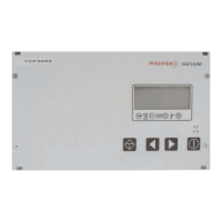
Connecting the OnTool Booster
50 TCP 3000 electronic drive unit
51 Bayonet plug --> TCP 3000
52 Connecting cable pump-TCP
53 Bayonet plug --> pump
X8 Connection gas ballast valve
50
53
X2
52
X7
51
X8
*
AAtttteennttiioonn!!
If using a turbopump
TPH 2303 no vent valve may be
connected to X8!
TTPPHH
22330033
 Loading...