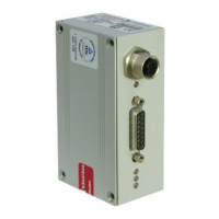
9
Pin Description/Explanation Function Type
1 + 24 V DC Reference voltage for all remote inputs and outputs
(potential free) -
2 Venting release Release “vent pump” Digital input
ON/OFF The pump is vented according to the “Vent mode P030” setting (static signal)
3 Motor TMP Switches the turbo pump drive on Digital input
ON/OFF (is only switched on if the function (static signal)
“pumping station P010” is also ON)
4 Pumping station Switches on pumping station Digital input
ON/OFF (rotor lifted from its rest position. When [P:023] “Motor TMP” (static signal)
is set to ON, the rotor accelerates.)
5 Standby rotation speed Rotor speed is limited to n % as per [P:717] Digital input
ON/OFF (factory setting 66 %) (static signal)
6n.c.
7 Rotation speed preset Rotation speed preset value in the range of 20-100 % Analog voltage
0-10 V DC of the “nominal rotation speed”[P:315] input 2-10 V DC; 0-2 V=f
nom
8 Switching output 1 [P:701] “rotation speed switch point” exceeded Active digital output
(Switch point) (I
max
= 50 mA/24 V)
9 Switching output 2 Function configurable with «019: Conf.Out2»; Active digital output
(error) factory setting “error output 24 V = no error (I
max
= 50 mA/24 V)
10 n.c.
11 Backing pump control 24 V = Backing pump on Active digital output
(I
max
= 50 mA/24 V)
12 Uf/Ui/Up Output voltage 0-10 V DC proportional; Analog voltage output
voltage output Rotor speed, motor current or drive power configurable 0-10 V DC / R
L
> 10 k
with «055: Conf A01»
13 Malfunction acknowledgment Deleting an error message Digital input (pulse 500...1000 ms)
14 Remote priority Remote functions have priority over operation Digital input
ON/OFF via RS-485. Must be activated with parameter [P:028] (static signal)
15 Relay contact Pin 15 and 16 connected Relay contact
switch point when the rotor speed is above switch point U
max
= 50 V DC
16 Relay contact Pin 16 and 17 connected I max = 1 A
Switch point when rotor speed is below switch point
17 Relay contact
Switch point
18 Relay contact Pin 18 and 19 connected Relay contact
Error if there is no error U
max
= 50 V DC
19 Relay contact Pin 19 and 20 connected I
max
= 1 A
Error if there is an error
20 Relay contact (For additional information see Chap. 6.15., Switching Outputs)
Error
21 n.c.
22 n.c.
23 n.c.
24 n.c.
25 n.c.
26 GND* Ground potential for all remote inputs and outputs
 Loading...