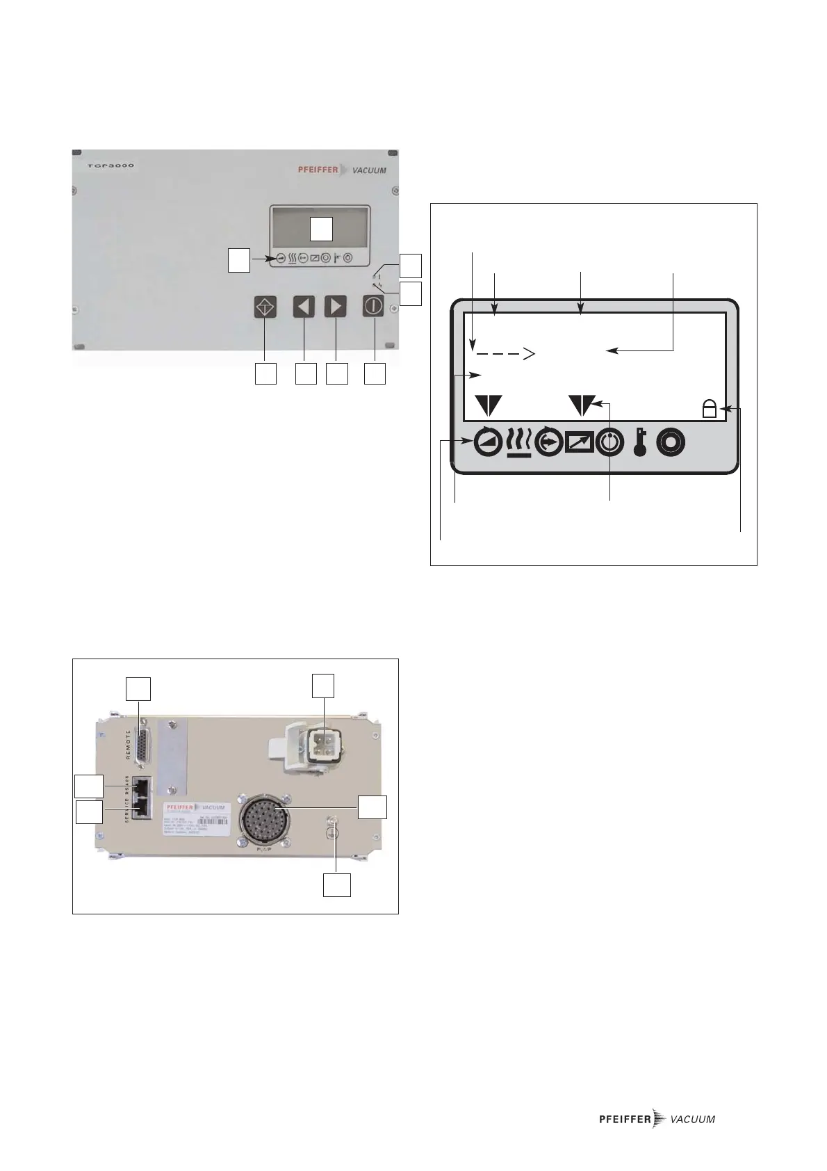
5
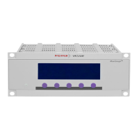
1 LC display, illuminated
2 Status display
3 Key “Acknowledge”
4 Parameter selection key “go back”
5 Parameter selection key “advance”
6 Key “Pump ON/OFF”
7 Red light emitting diode for error status
8 Green light emitting diode for operational status
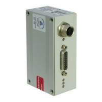
11 Connector remote control (REMOTE)
12 Connector RS-485 interface
13 Connector RS-232 service interface (SERVICE)
14 Ground terminal PE
51 Mains connection (185-265 V AC), (AC INPUT)
53 Bayonet plug Turbopump (PUMP)
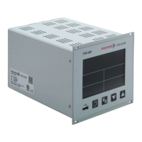
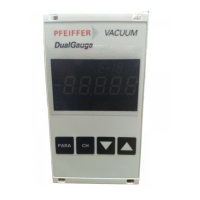
2.3. Description of the Front Panel
All controls and display components are located on the front
panel.
2.4. Description of the Rear Panel
2.5. General Description of the Unit
The electronics of the TCP 3000 electronic drive unit provides
for a number of monitoring and control options for turbomole-
cular pumps and for the pumping process. The drive unit may
be operated either through keyboard, serial interface or
remote control unit.
Through the LC display, various operating modes can be
displayed. The way in which the vacuum components operate
is controlled through parameters, i.e. through certain
combinations of numbers to which a function has been assig-
ned. The parameters which may be selected are detailed in
the parameter overviews of Chapter 5.2 and 5.3.
Parameter Sets
The parameters can be invoked from two different parameter
sets (see also the descriptions in Chapter 5.1):
– Basic parameter set
– Expanded parameter set
Parameter Types
There are three types of parameters:
– Adjustment commands
– Status queries
– Setpoint presets
The factory default settings may either be retained, or under
“Adjustment commands” and “Setpoint presets” the user
may enter his own settings. When wanting to enter presets or
change operating modes, the information given in Chapter 6
“Operation” must be noted.
Operation via remote control is detailed in Chapter 6.9, Opera-
tion involving the interface is detailed in Chapter 6.11.
 Loading...