CABINET DISASSEMBLY INSTRUCTIONS
1. Disassembly Flowchart
This flowchart indicates the disassembly steps to gain
access to item(s) to be serviced. When reassembling,
follow the steps in reverse order. Bend, route, and dress
the cables as they were originally.
Disassembly Method
ID/
LOC.
No.
PART
REMOVAL
Fig.
No.
REMOVE/
*UNHOOK/UNLOCK/
RELEASE/UNPLUG/
DESOLDER
Note
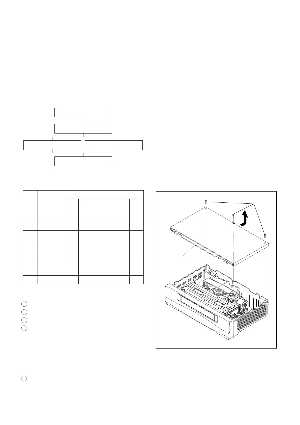
[1] Top Case 1 3(S-1) -
[2]
Front
Assembly
2 *3(L-1), *4(L-2)
-
[3]
Function
CBA
2, 3 *(L-3), *(CN505)
1
[4]
Deck
Assembly
4 5(S-2), *(CN251,
CN501, CN502,
CN503, CN504)
2, 4
[5] Main CBA 5 3(S-3), *3(L-4) 3
↓
➀
↓
➁
↓
➂
↓
➃
↓
➄
Reference Notes
CAUTION: Locking Tabs (L-1) and (L-2) are fragile. Be
careful not to break them.
1. Disconnect Connector (CN505) to remove Function
CBA. Hold Main CBA while pulling up on the Func-
tion CBA. (Fig. 3)
2. Remove five Screws (S-2). Then slowly lift the Deck
Assembly up. Lifting Deck Assembly disconnects
five Connectors (CN251, CN501, CN502, CN503,
CN504). (Fig. 4)
3. When reassembling the unit, always reinsert three
Locking Tabs (L-4), and then reinstall two Screws
(S-3). These screws are critical for proper shielding
of the Main CBA. (Fig. 5)
4. Before installing the Deck Assembly, be sure to align
two triangle marks of LD-SW on Main CBA. Then,
install the Deck Assembly while aligning the hole of
Cam Gear with the pin of LD-SW, the shaft of Cam
Gear with the hole of LD-SW as shown in Fig. 6.
[1] Top Case
[2] Front Assembly
[3] Function CBA [4] Deck Assembly
[5] Main CBA
(S-1)
[1]Top Case
Fig. 1
1 : Identification (location) No. of parts in the figures
2 : Name of the part
3 : Figure Number for reference
4 : Identification of parts to be removed, unhooked, un-
locked, released, unplugged, unclamped, or
desoldered.
P=Spring, L=Locking Tab, S=Screw,
CN=Connector
*=Unhook, Unlock, Release, Unplug, or Desolder
e.g. 2(S-2) = two Screws (S-2),
2(L-2) = two Locking Tabs (L-2)
5 :Refer to "Reference Notes."
1-8-1 H67T0DC
www.freeservicemanuals.info