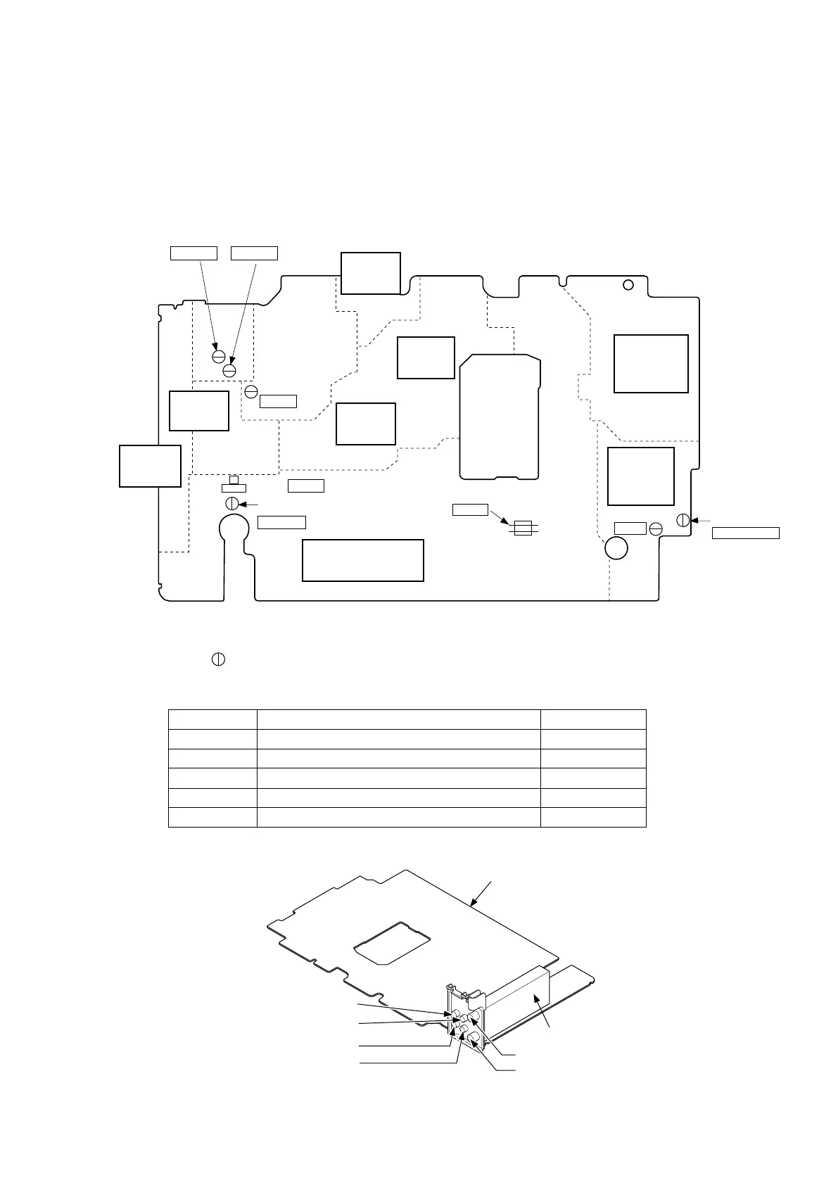
TEST POINT INFORMATION
: Indicates a test point with a jumper wire across a hole in the PCB.
1-9-2 H67T0AP
Main CBA Top View
Adjustment Points and Test Points
POWER
SUPPLY
BLOCK
AUDIO
BLOCK
VIDEO
BLOCK
SYSCON/TIMER
SERVO BLOCK
TP302
RF-SW
J267
GND
SW507
TP506
ST-S
TP303
CTL
TP301
C-PB
TP751
V-OUT
TP752
A-OUT
Hi-Fi
BLOCK
VR501 SW-P
TP502
SENS-INH
Test Point
TP301
TP302
TP303
J267
TP502
Used in: Page No.
Mechanical Alignment Procedures
Mechanical Alignment Procedures
Mechanical Alignment Procedures
Preparation for Servicing
Preparation for Servicing
2-3-3, 2-3-4
2-3-3, 2-3-4
2-3-3
1-5-1
1-5-2
TEST POINTS NOT USED IN ELECTRICAL ADJUSTMENTS
TP572
END-S
Tuner Unit
Main CBA
Antenna In
Video In
Audio In
Audio Out
Video Out
Antenna Out
TUNER
BLOCK
OSD
BLOCK
POWER
CTL
BLOCK
H-AMP
BLOCK
www.freeservicemanuals.info