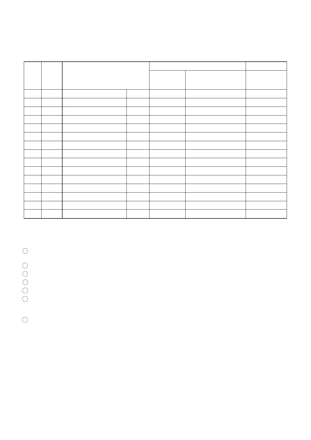
Front Loading Assembly
Before following the procedures described below, be sure to remove Front Loading Assembly from the main
mechanism of the deck assembly. (See Fig. DM3.) When reassembling, follow the steps in reverse order.
STEP
/LOC.
No.
START-
ING
No.
PART
REMOVAL INSTALLATION
Fig. No.
REMOVE/*UNHOOK/
UNLOCK/RELEASE/
UNPLUG/DESOLDER
ADJUSTMENT
CONDITION
[1] [1] Guide Holder T DM17 2(S-1), *2(L-1)
[2] [1] Slider Gear L, R DM16, DM17 *4(L-2) Eject Position
*[3] [2] Slider Shaft T DM16, DM17 Eject Position
[4] [4] Cassette Plate T DM17 2(S-2)
[5] [4] Slider L T DM17
[6] [4] Slider R T DM17 (S-3)
[7] [6] Door Opener A R DM17
[8] [8] Lock Lever B DM17 (S-4), *(P-1)
[9] [3] Cassette Guide R R DM17
[10] [3] Cassette Guide L L DM17
[11] [11] Joint Holder A R DM17 (S-5), *(P-2)
[12] [11] Cassette Drive Sub Gear R DM17, DM18 Eject Position
[13] [11] Cassette Drive Gear R DM17, DM18 Eject Position
[14] [13] Cassette Drive Lever R DM17 Cassette Drive Spring Eject Position
[15] [14] Front Door Opener R DM17, DM18 *(L-3)
↓
➀
↓
➁
↓
➂
↓
➃
↓
➄
↓
➅
↓
➆
1 : Follow steps in sequence. When reassembling, follow the steps in reverse order.
These numbers are also used as Identification (location) No. of parts in the figures.
2 : Indicates the part to start disassembling with in order to disassemble the part in column (1).
3 : Name of the part
4 : Location of the part: T=Top B=Bottom R=Right L=Left
5 : Figure Number
6 : Identification of parts to be removed, unhooked, unlocked, released, unplugged, unclamped, or desoldered.
P=Spring, W=Washer, C=Cut Washer, S=Screw, *=Unhook, Unlock, Release, Unplug, or Desolder
e.g., 2(L-2) = two Locking Tabs (L-2).
7 : Adjustment Information for Installation
(+): Refer to Deck Exploded Views for lubrication.
*[3]: They are divided into two steps because, before reassembling Slider Shaft, one Slider Gear must be preinstalled
at either end of Slider Shaft.
2-4-8 MK9FL
www.freeservicemanuals.info