ELECTRICAL ADJUSTMENT INSTRUCTIONS
General Note: "CBA" is an abbreviation for "Circuit
Board Assembly".
Notes:
1.Electrical adjustments are required after replacing
circuit components and certain mechanical parts. It
is important to do these adjustments only after all
repairs and replacements have been completed.
Also, do not attempt these adjustments unless the
proper equipment is available.
2.To perform these alignment / confirmation proce-
dures, make sure that the tracking control is set in
the center position: Press either channel "▼" or "▲"
button first, then the " PLAY " button (VCR’s Front
Panel only).
Test Equipment Required
1.Oscilloscope: Dual-trace with 10:1 probe, V-Range:
0.001~50V/Div., F-Frange: AC~DC-20MHz
2.Alignment Tape ( 4822 395 10283 )
1. Head Switching Position
Adjustment
Purpose: To determine the Head Switching point dur-
ing playback.
Symptom of Misadjustment: May cause Head
Switching noise or vertical jitter in the picture.
Test Point Adj. Point Mode Input
TP751(V-OUT)
TP302(RF-SW)
GND
VR501 (SW-P)
PLAY
(SP)
----
Tape
Measurement
Equipment
Spec.
4822 395 10283 Oscilloscope
6.5H±1H
(412.7±60µs)
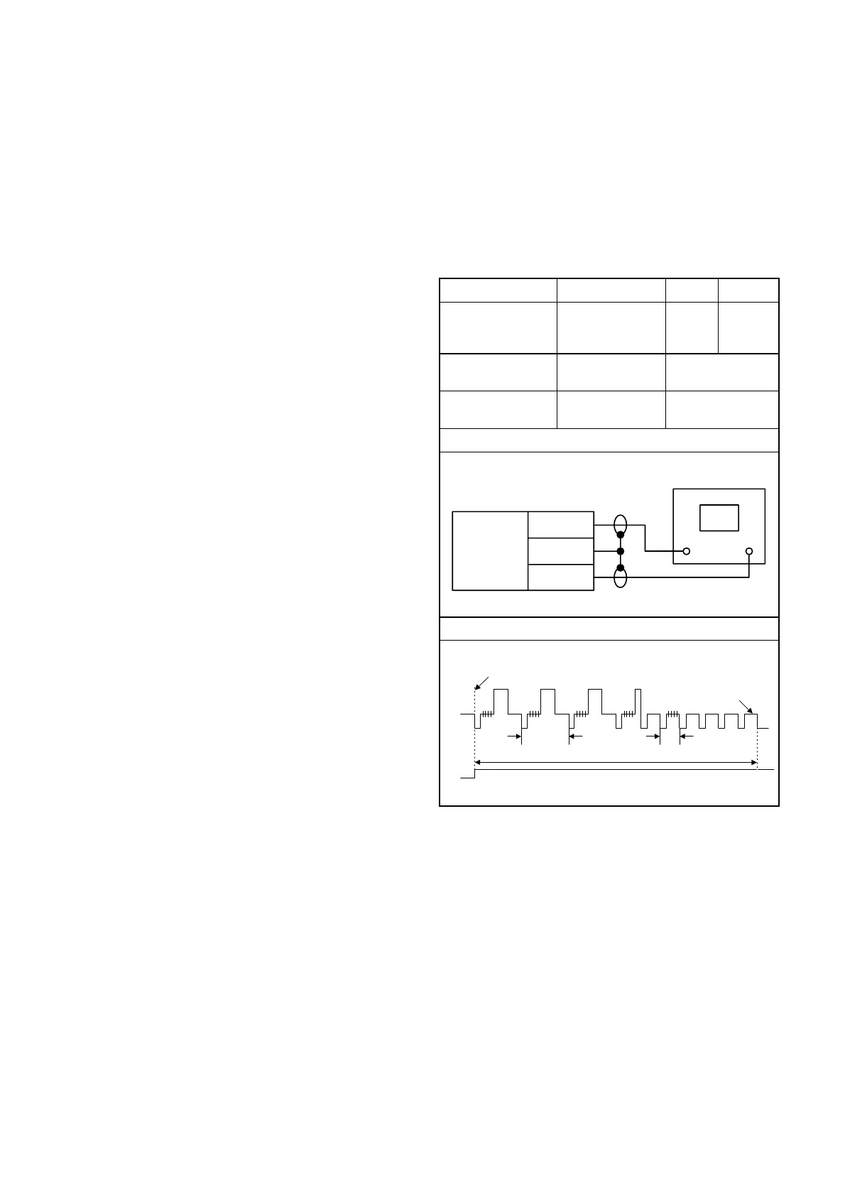
Connections of Measurement Equipment
Figure 1
Reference Note:
TP302, TP751, VR501 : Main CBA
• Play back the test tape and adjust VR501 so that the
V-sync front edge of the CH1 video output wave-
form is at the 6.5H(412.7µs) delayed position from
the rising edge of the CH2 head switching pulse
waveform.
EXT. Synchronize Trigger Point
V-Sync
0.5H1.0H
6.5H
Switching Pulse
CH2
CH1
GND
Main CBA
TP302
TP751
CH1 CH2
Oscilloscope
Trig. (+)
1-9-1 H67T0EA
www.freeservicemanuals.info