1-11-15
1-11-16 1-11-17
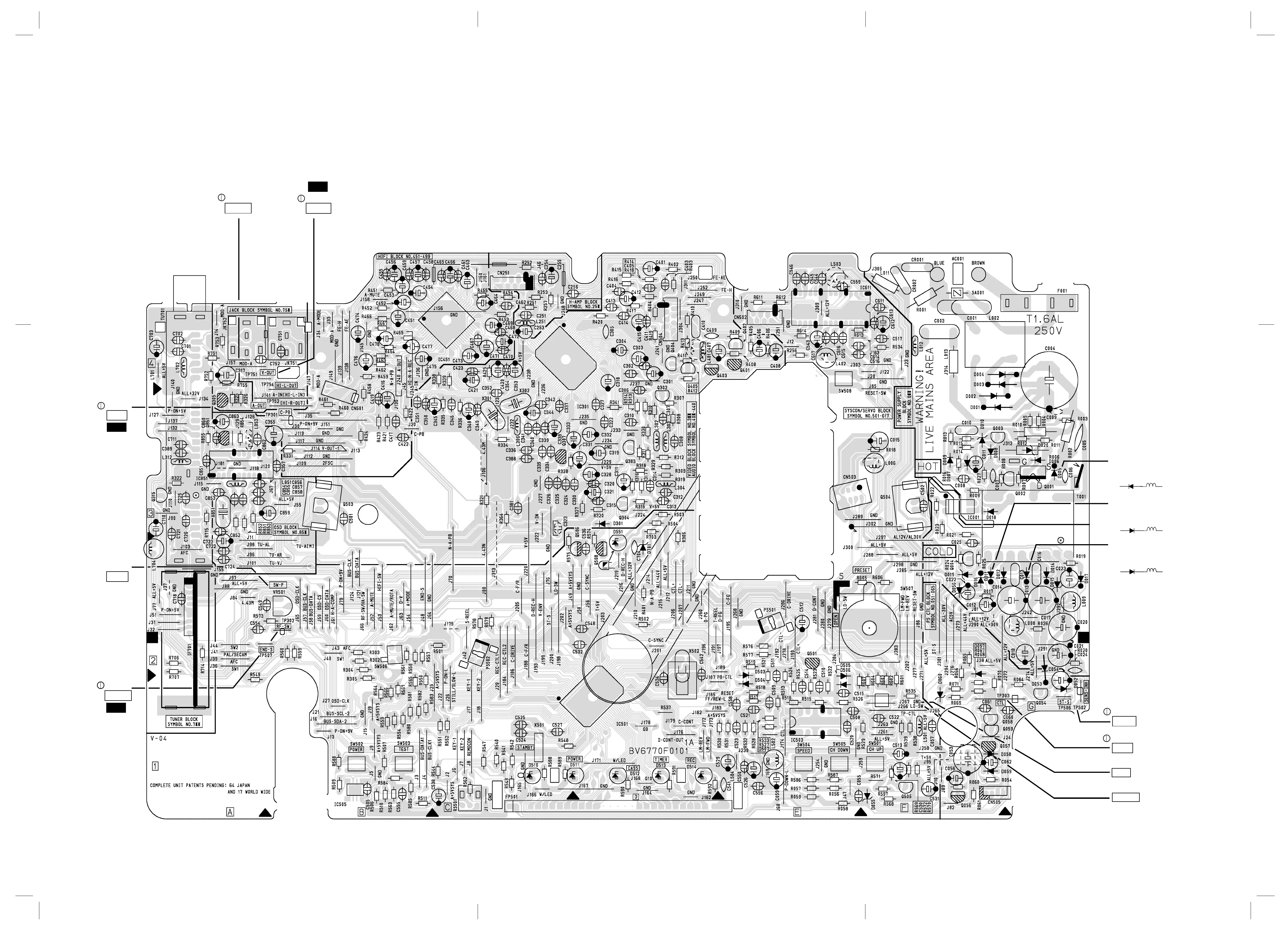
Main CBA Top View
BV6770F01011-A
WF1
TP751
V-OUT
TP752
A-OUT
VR501
SW-P
WF2
TP302
RF-SW
WF5
TP301
C-PB
TP303
CTL
TP502
S-INH
Note: L007 is positioned
on the Cathode side of
D013 as shown below.
D013 L007
Note: L004 is positioned
on the Cathode side of
D011 as shown below.
D011 L004
BECAUSE A HOT CHASSIS GROUND IS PRESENT IN THE POWER
SUPPLY CIRCUIT , AN ISOLATION TRANSFORMER MUST BE USED.
ALSO , IN ORDER TO HAVE THE ABILITY TO INCREASE THE INPUT
SLOWLY , WHEN TROUBLESHOOTING THIS TYPE POWER SUPPLY
CIRCUIT , A VARIABLE ISOLATION TRANSFORMER IS REQUIRED.
NOTE :
THE VOLTAGE FOR PARTS IN HOT CIRCUIT IS MEASURED USING
HOT GND AS A COMMON TERMINAL.
CAUTION
FOR CONTINUED PROTECTION AGAINST FIRE HAZARD,
REPLACE ONLY WITH THE SAME TYPE FUSE.
CAUTION !
Fixed voltage (or Auto voltage selectable ) power supply circuit is used in this unit.
If Main Fuse (F001) is blown, check to see that all components in the power supply
circuit are not defective before you connect the AC plug to the AC power supply.
Otherwise it may cause some components in the power supply circuit to fail.
WF2
TP302
RF-SW
Note: L003 is positioned
on the Anode side of
D005 as shown below.
D005 L003
J267
GND
J266
LD-SW
www.freeservicemanuals.info