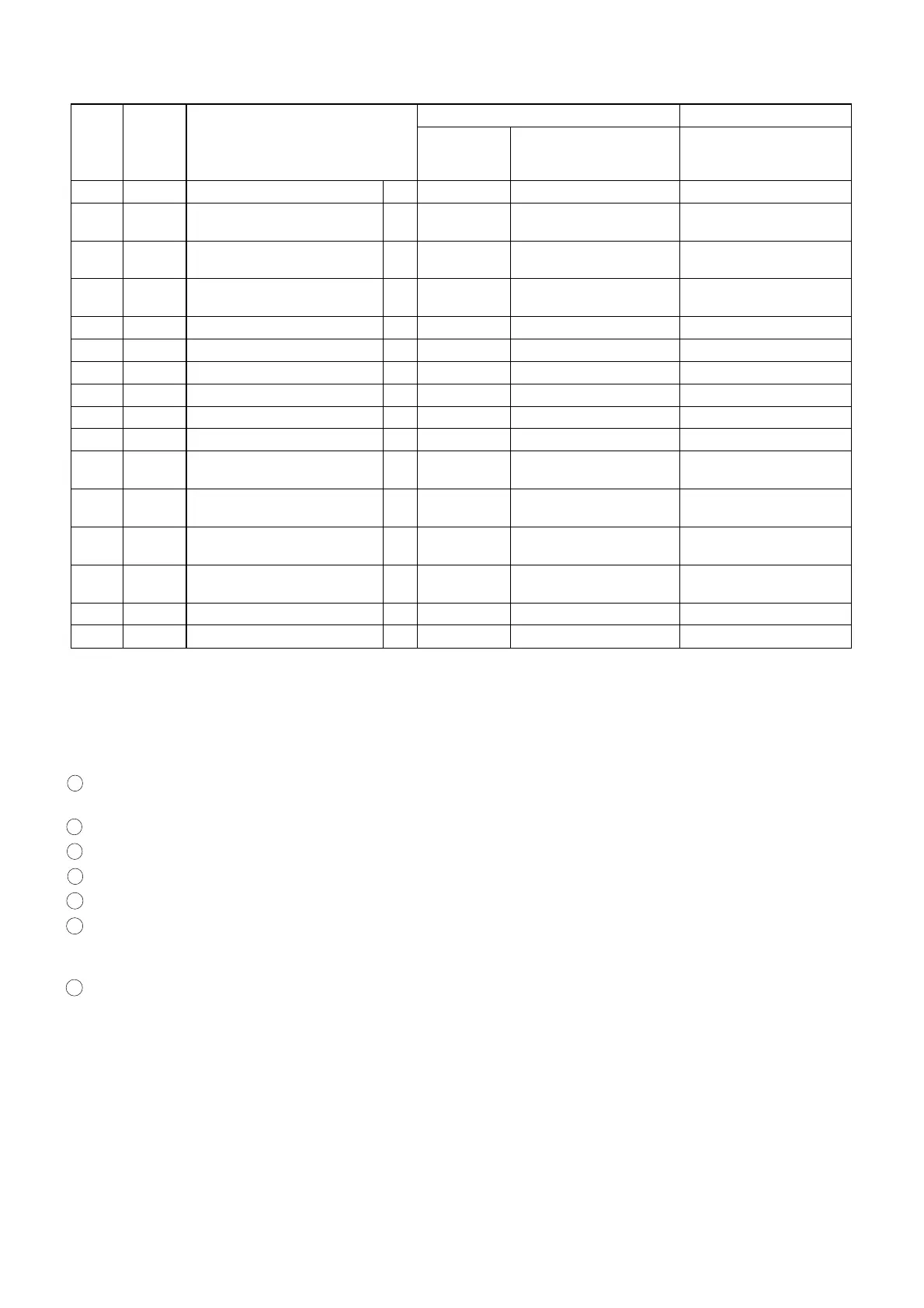
1 : Follow steps in sequence. When reassembling, follow the steps in reverse order.
These numbers are also used as Identification (location) No. of parts in the figures.
2 : Indicates the part to start disassembling with in order to disassemble the part in column (1).
3 : Name of the part
4 : Location of the part: T=Top B=Bottom R=Right L=Left
5 : Figure Number
6 : Identification of parts to be removed, unhooked, unlocked, released, unplugged, unclamped, or desoldered.
P=Spring, W=Washer, C=Cut Washer, S=Screw, *=Unhook, Unlock, Release, Unplug, or Desolder
e.g., 2(L-2) = two Locking Tabs (L-2).
7 : Adjustment Information for Installation
(+): Refer to Deck Exploded Views for lubrication.
STEP
/LOC.
No.
START-
ING
No.
PART
REMOVAL INSTALLATION
Fig. No.
REMOVE/*UNHOOK/
UNLOCK/RELEASE/
UNPLUG/DESOLDER
ADJUSTMENT
CONDITION
[31] [30] Tension Lever Assembly T DM1, DM11 *(P-7), (C-6)
[32] [31]
Tension Lever Sub
Assembly
T DM1, DM11
[33] [31]
Reel S Assembly T DM1, DM11 (C-7),
Poly Slider Washer
[34] [29]
Reel T Assembly T DM1, DM11 (C-8),
Poly Slider Washer
[35] [33] Reel Shaft T DM1, DM11 2(S-19)
[36] [18] First Gear B DM2, DM12 (C-9)
[37] [36] Second Gear B DM2, DM12 (C-10), (W-2)
[38] [37] FF Arm T DM1, DM13
[39] [37] Idler Assembly T DM1, DM13
[40] [37] BT Arm Assembly B DM2, DM14
[41] [19]
Loading Arm T Assembly B DM2, DM14 (C-11) (+) Refer to Alignment
Sec. Pg. 2-4-10
[42] [41]
Loading Arm S Assembly B DM2, DM14 (+) Refer to Alignment
Sec. Pg. 2-4-10
[43] [2]
Moving Guide S
Preparation
T DM1, DM15
[44] [2]
Moving Guide T
Preparation
T DM1, DM15
[45] [2] Cleaner Lever Assembly T DM1, DM4
[46] [45] CL Post T DM1, DM4
↓
➀
↓
➁
↓
➂
↓
➃
↓
➄
↓
➅
↓
➆
2-4-2 H67T0DA
www.freeservicemanuals.info