AXC F X152
58 / 104
PHOENIX CONTACT 107708_en_09
6.2 User interface
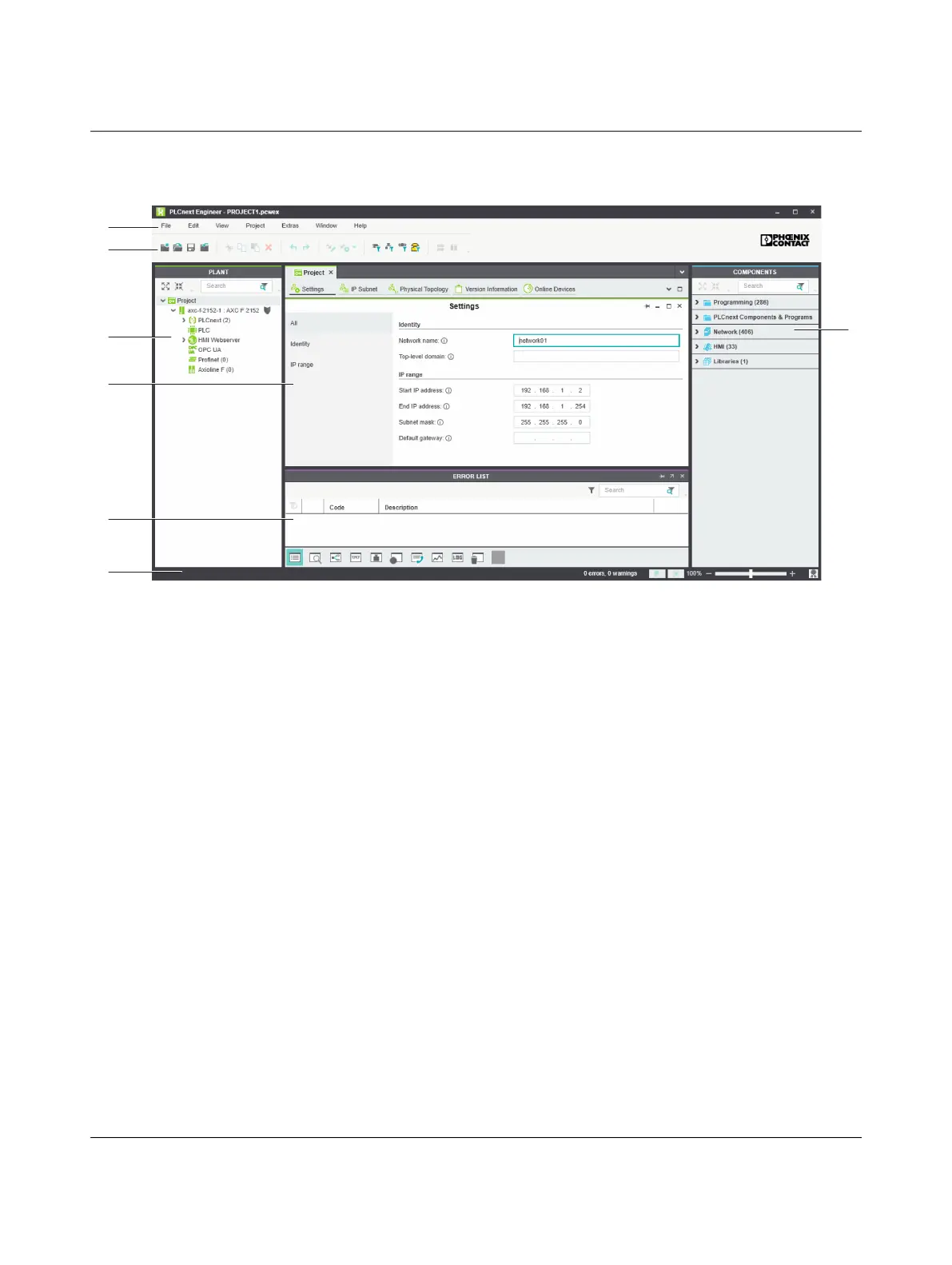
Figure 6-1 PLCnext Engineer user interface
1. Menu bar
2. Tool bar
3. “PLANT” area
4. Editors area
5. “COMPONENTS” area
6. Cross-functional area
7. Status bar
“PLANT” area All of the physical and logical components of your application are mapped in the form of a
hierarchical tree structure in the “PLANT” area.
Editors area Double-clicking on a node in the “PLANT” area or an element in the “COMPONENTS” area
opens the associated editor group in the Editors area. Editor groups are always displayed
in the center of the user interface. The color of the editor group indicates whether it is an in-
stance editor (green; opened from the “PLANT” area) or a type editor (blue; opened from
the “COMPONENTS” area). Each editor group contains several editors that can be opened
and closed via buttons in the editor group.
“COMPONENTS”
area
The “COMPONENTS” area contains all of the components available for the project. The
components can be divided into the following types based on their function:
– Developing program code (“Data Types”, “Programs”, and “Functions & Function
Blocks”)
– Displaying all devices available for the “PLANT” area and adding them via GSDML or
FDCML (“Devices”)
– Editing HMI pages (“HMI”)
 Loading...


