Mounting hardware
107708_en_09 PHOENIX CONTACT 47 / 104
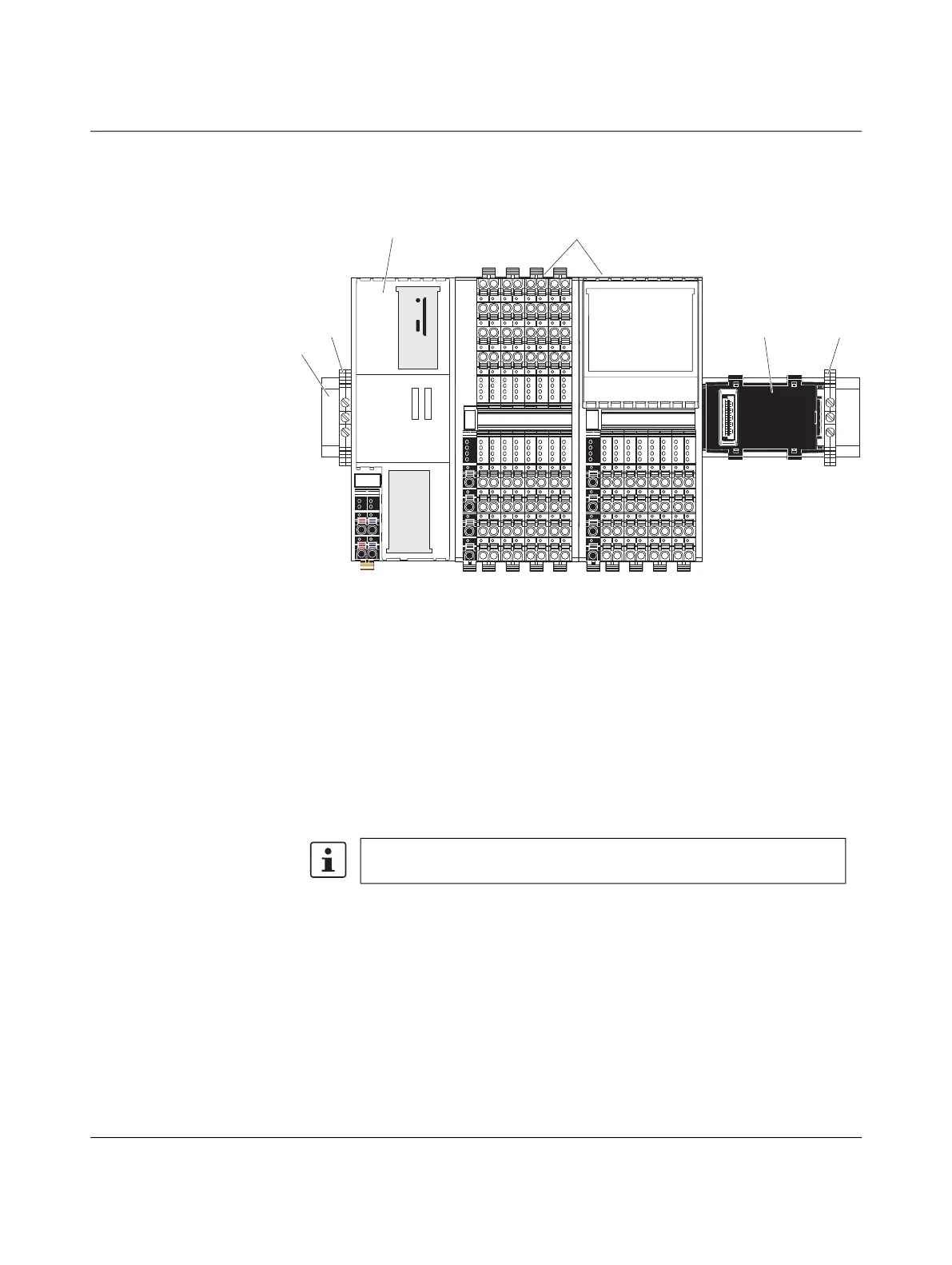
4.3 Structure of an Axioline F station
Figure 4-3 shows an example structure of an Axioline F station with the AXC F 2152:
Figure 4-3 Example: Structure of an Axioline F station with the AXC F 2152
Key:
1 DIN rail
2 End bracket (e.g., CLIPFIX 35-5; Order No. 3022276)
3 Controller
4 I/O modules (Axioline F devices) corresponding to the application
5 Bus base module
An Axioline F station is set up by mounting the individual components side by side. No tools
are required. Mounting the components side by side automatically creates potential and bus
signal connections between the individual components of the Axioline F station.
Left-alignment of
Axioline F extension
modules
For additional information on the number and order of left-alignable
Axioline F extension modules, refer to page 15.
 Loading...


