5756B
INTERBUS Process Data in the PLC
The I/O address area of the SIMATIC
®
S7-300 PLC depends
on the type of CPU. It is split into an input and an output
address area. These contain the data of the boards operated
in the PLC.
Driver blocks allow the area of the INTERBUS process data
(input and output data of INTERBUS devices) to be
transferred into or out of the S7-300 PLC block by block. The
driver blocks create a process image that reads the inputs
prior to the application program, and writes the outputs to the
controller board or output devices after they have been
processed by the application program.
The driver can transfer the input/output data of the
INTERBUS system into the I/Q area of the PLC, bit memory
areas or data blocks, or out of these areas.
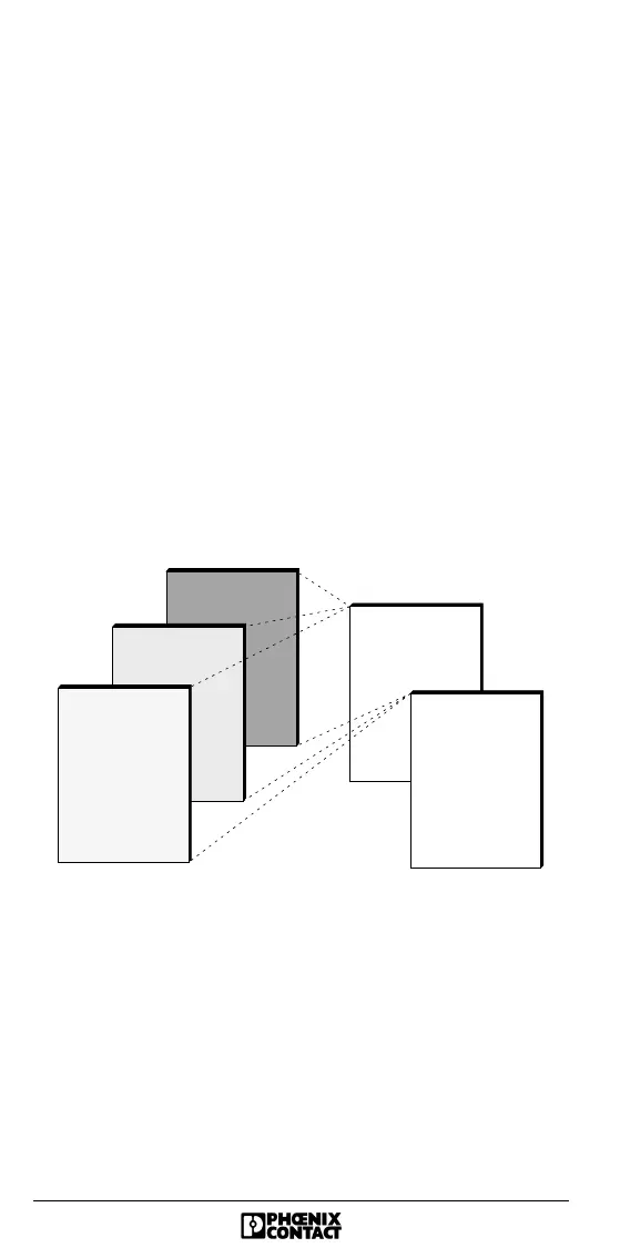
Addressable Areas of the SIMATIC
®
S7-300
5770B013
Data block
Bit memory area
I/Q area
INTERBUS
m ax. 512 output
bytes
IN T E R B U S
(process im age)
area
input area
output area
(m ax. 512 input
bytes)