18 5756B
Example of an INTERBUS and PLC
Configuration
To make your introduction to working with the
IBS S7 300 DSC-T controller board as straightforward as
possible, the descriptions in later sections are based on the
following INTERBUS and PLC configuration.
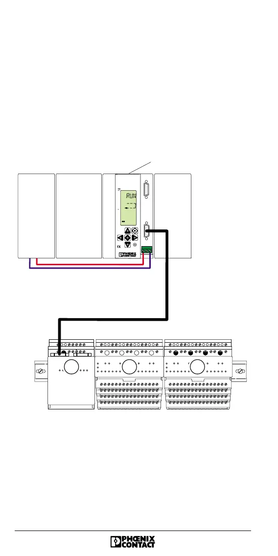
Example Configuration
Figure 17 Example configuration
F
E
F
E
F
E
F
E
B us term inal
module
IB S T 2 4 B K -T
ID : 8 (8 h )
16 digital
in p u ts
IB S T 2 4 D I 1 6 /4
ID : 190 (BEh)
16 digital
outputs
IB S T 24 D O 16/3
ID : 189 (BD h)
21 3
5756A 018
IB S S 7 3 0 0 D S C -T
CPU
IN
I
NTER
B
US
IB S S 7 3 0 0 D S C - T
O r d .N o .: 2 7 1 9 9 7 5
STOP
7
6
5
4
3
2
1
0
7
6
5
4
3
2
1
0
PS
INTERBUS