5756B 5
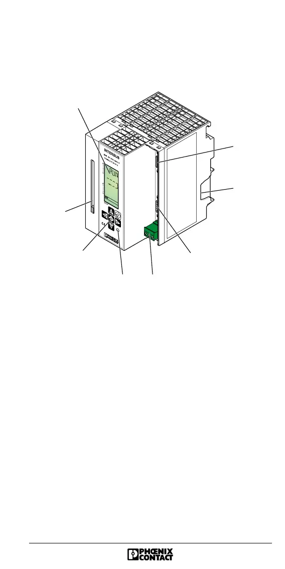
Structure of the Controller Board
Connecting and Operating Elements
Figure 1 Front view
Key
1 LCD
2 Slot for the parameterization memory **
3 Operator’s panel *
4 Test mode button
5 Connection for external power supply (24 V DC)
6 Remote bus interface (9-pos. D-SUB female connector)
7 Location for the outgoing SIMATIC
®
bus connector
8 Diagnostic interface
(9-pos. D-SUB male connector, for connection to a PC)
* Operation: see back cover or IBS SYS DIAG DSC UM E
Diagnostics Guide
** The parameterization memory is not shipped together
with the controller board.
1
2
45
3
7
6
8
5756A002