Description of I/O extension modules
105542_en_05 PHOENIX CONTACT 107 / 198
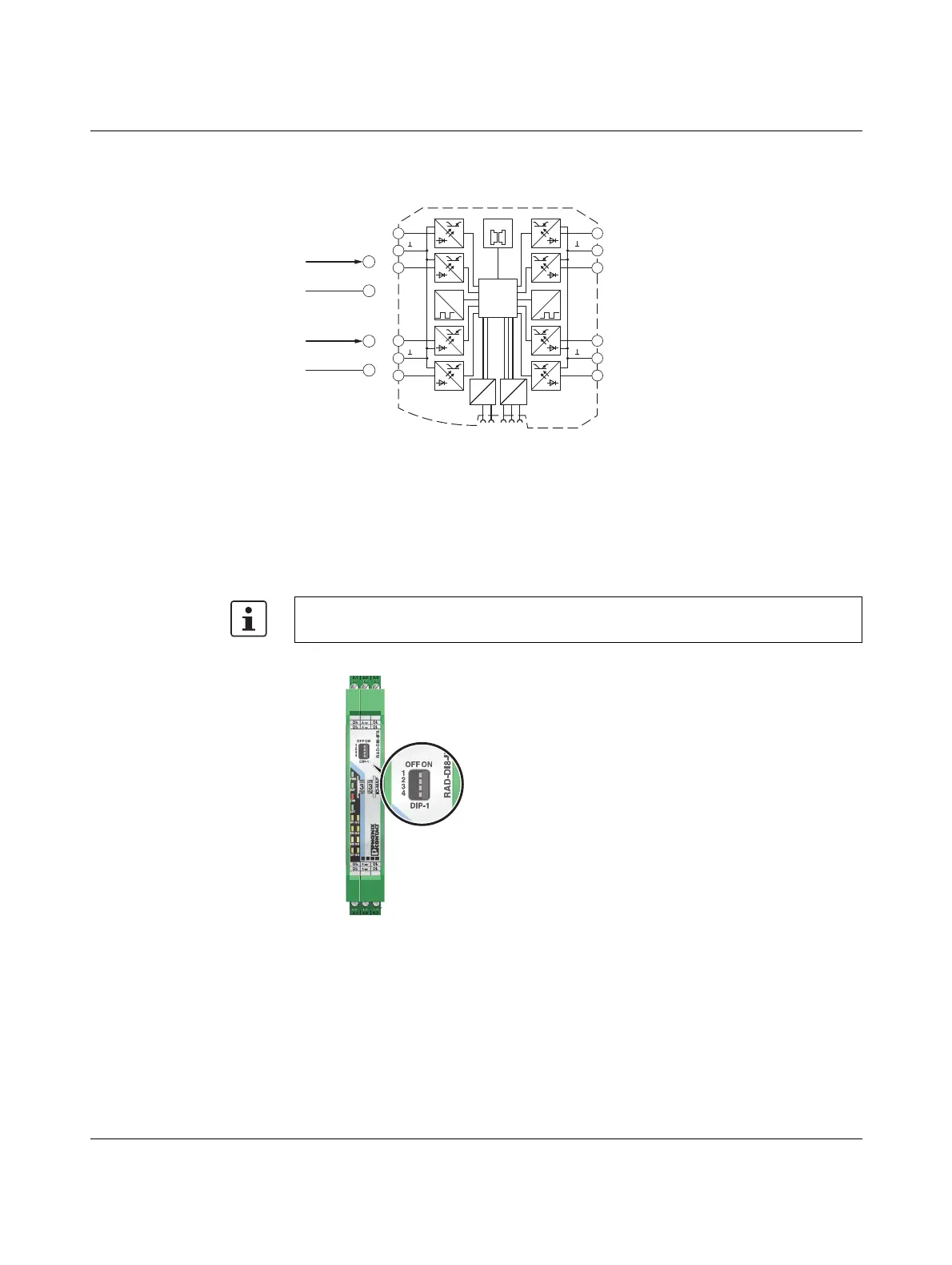
7.5.2 Basic circuit diagram
Figure 7-22 Basic circuit diagram for the RAD-DI8-IFS
7.5.3 Setting the DIP switches
Select static mode or pulse counter mode using the DIP switches on the front.
– In static mode, inputs DI1 ... DI8 are activated, 0 V ... 30.5 V DC voltage
– In pulse counter mode, pulse inputs DI1 and DI7 are activated, 0 Hz ... 100 Hz pulses
Figure 7-23 DIP switches of the RAD-DI8-IFS
The pulse counter function is only available in PLC / Modbus/RTU mode and in dual
mode. Set the operating mode using the PSI-CONF software (from page 35).
0...100 Hz
2.1
2.2
GND
0...30,5 VDC
2.1
2.2
GND
µC
2.1
2.2
2.3
3.1
3.2
3.3
5.1
5.2
5.3
4.1
4.2
4.3
IO-MAP
0
1
DC
DC
IFS
IFS
CNT CNT
DI
2
DI
4
DI
1
DI
3
DI
8
DI
6
DI
7
DI
5
1-4
1-4
5-8
5-8
Pulse:
Static:

 Loading...