RAD-...-IFS
136 / 198
PHOENIX CONTACT 105542_en_05
8.8.1 Outdoor installation of antennas
Antenna cables and antennas are directly exposed to atmospheric discharge. The anten-
nas and the entire infrastructure should therefore be protected against discharge. Protec-
tive devices with Lambda/4 technology are usually used for this. These surge protective de-
vices have a coaxial design. They are suitable for all standard transmission systems. Low
attenuation and high bandwidth are simultaneously achieved by means of low-capacitance
protective circuits. Thanks to excellent impedance matching, surge protection does not dis-
tort the useful signal.
• Use surge protection for installation outdoors.
– For RAD-2400-IFS...: CN-LAMBDA/4-5.9-BB, Order No. 2838490
– For RAD-868-IFS: CN-LAMBDA/4-2.2-BB, Order No. 2800024
• The antenna is grounded via the surge protection device.
• The antenna mast must be grounded in accordance with national regulations.
• In outdoor applications, use RAD-TAPE-SV-19-3 vulcanizing sealing tape (Order No.
2903182) to protect adapters, cable connections, etc.
• Run the antenna cable inside the mast or fasten it to the outside of the mast with
UV-resistant cable binders.
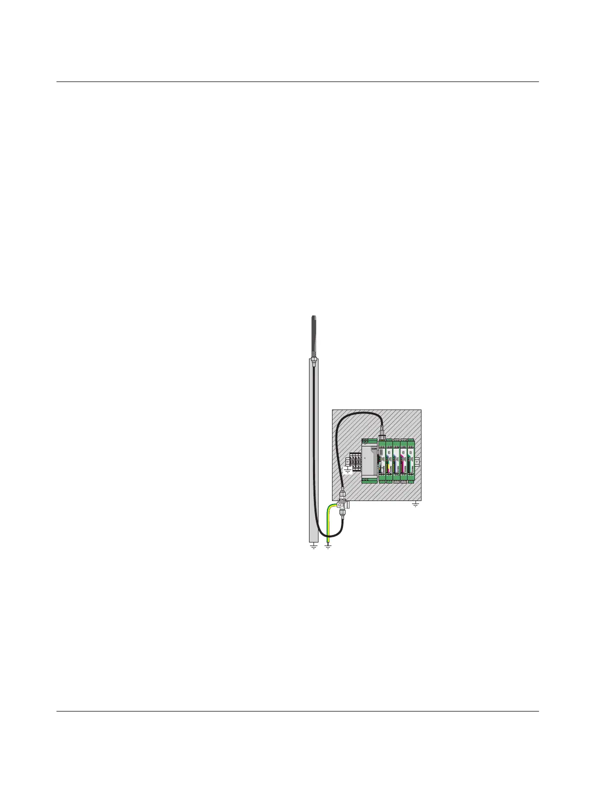
Figure 8-8 Outdoor installation of antennas
1 Omnidirectional antenna
2 Antenna cables
3 Antenna mast
4 Antenna surge protection
5 Control cabinet
6 Power supply, wireless module, and I/O extension modules
MINI SYS POWER
DC
OK
L NC N
IN AC 100-240V
OUT DC 24V 1.5A
24V 13 14
24V 0V 0V
RAD-2400-IF
S
RAD-ID
S-POR
T
PWR
DAT
ERR
RXTX
0
1
SET
D(A)
D(B)
RX
COM
1
TX
NO
2
GND
NC
1
+24V
RSSI
+
0V
ANT
RSSI
-
RAD-DAIO6-IFS
IO-MAP
OFF ON
DIP-1
1
2
3
4
PWR
DAT
ERR
DO4
DO3
DO2
DO1
DI1L
DI2L
DI1H
DI2H
DI1
DI2
UL1 +I1 -I1
U1 I1
1
COM1
COM2
NO1
NO2
NC1
NC2
1 2
RAD-DOR4-IF
S
8 8
IO-MAP
PWR
DAT
ERR
DO4
DO3
DO2
DO1
OFF ON
DIP-1
1
2
3
4
COM1
NO1
NC1
COM2
NO2
NC2
COM3
NO3
NC3
COM4
NO4
NC4
RAD-DI4-IFS
DI1L
DI2L
DI1H
DI2H
DI1
DI2
PWR
DAT
ERR
DI4
DI3
DI2
DI1
DI3L
DI4L
DI3H
DI4H
DI3
DI4
8 8
IO-MAP
RAD-AI4-IFS
PWR
DAT
ERR
2 2
IO-MAP
OFF ON
DIP-1
1
2
3
4
Pwr1
Pwr2
+I1
+I2
-I1
-I2
Pwr3
Pwr4
+I3
+I4
-I3
-I4
1
2
4
3
5
6

 Loading...