RAD-...-IFS
20 / 198
PHOENIX CONTACT 105542_en_05
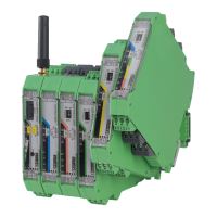
3.2 Basic circuit diagram
Figure 3-2 Basic circuit diagram for the wireless module
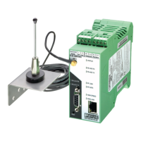
3.3 Mounting and removal
You can connect up to 32 different I/O extension modules to each wireless module via the
DIN rail connector. Data is transmitted and power is supplied to the I/O extension modules
via the bus foot.
When using the device in a connection station, use the supplied 17.5 mm DIN rail connec-
tor. Only use the DIN rail connector in conjunction with 24 V DC devices.
Figure 3-3 Radioline connection station with up to 32 I/O extension modules
– Mount the wireless module to the left and the I/O extension modules only to the right
of the wireless module.
– The individual extension modules can be arranged in any order.
– 2.4 GHz wireless modules only: install the wireless module at least 1 m away from
other devices using the 2.4 GHz frequency band (e.g., WLAN, Bluetooth, microwave
ovens). Otherwise, both the link quality and the data transmission speed will be re-
duced.
RF
5.1
5.2
5.3
RX
TX
RS232
GND
4.1
4.2
D(A)
D(B)
RS485
RAD-ID
S-Port
1.2
1.1
+24 V
0 V
2.1
2.2
RSSI+
RSSI-
U
IFS
IFS
µC
6.1
6.2
6.3
NC
1
NO
1
COM
1
DC
DC

 Loading...