Installation
105542_en_05 PHOENIX CONTACT 23 / 198
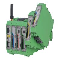
3.5 Connecting the power supply
Via screw terminal blocks
Connect a DC voltage source (19.2 V ... 30.5 V DC) to the wireless module. The nominal
voltage is 24 V DC. Supply voltage to the device via terminal blocks 1.1 (24V) and 1.2(0V).
In the case of a connection station, it is sufficient to supply the first device in the group.
Figure 3-6 Connecting the power supply
In order to prevent damage to the wireless module, we recommend installing a surge pro-
tective device. Make sure the wiring between the surge protective device and the wireless
module is as short as possible. Please also observe the manufacturer’s specifications.
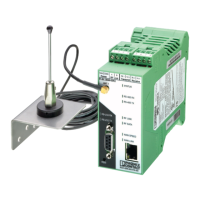
With a system power supply via the bus foot
If DIN rail connectors are used, you can use the MINI-SYS-PS 100-240AC/24DC/1.5 sys-
tem power supply (Order No. 2866983). Connect the system power supply using two DIN
rail connectors to the left of the device.
Figure 3-7 Supply via system power supply
– Parallel supply via the screw terminal blocks and with a system power supply via the
bus foot is not possible.
– For redundant supply, you can connect a second MINI-SYS-PS 100-240AC/24DC/1.5
system power supply.
+
2
4
V
R
S
S
I
+
R
S
S
I
-
A
N
T
C
O
M
1
N
O
1
N
C
1
R
X
T
X
G
N
D
D
(
A
)
D
(
B
)
Reset
RAD-ID
RAD-2400-IFS
S.PO
RT
8
8
PW
R
DA
T
ERR
RX TX
0
V
1
.1
1
.
2
R
S
S
I+
R
S
S
I
-
MINI SYS POWE
R
OUT DC 24 V 1,5 A
DC
OK
2
4
V
1
3
1
4
2
4
V
0
V
0
V
IN AC 100-240V
L NC N(-)
+
2
4
V
R
S
S
I+
R
S
S
I-
A
N
T
C
O
M
1
N
O
1
N
C
1
R
X
T
X
G
N
D
D
(
A
)
D
(B
)
Reset
RAD-ID
RAD-2400-IFS
S.PORT
8
8
PW
R
DA
T
ERR
RX TX
0
V
+
2
4
V
0
V
R
S
S
I+
R
S
S
I-
 Loading...