RAD-...-IFS
116 / 198
PHOENIX CONTACT 105542_en_05
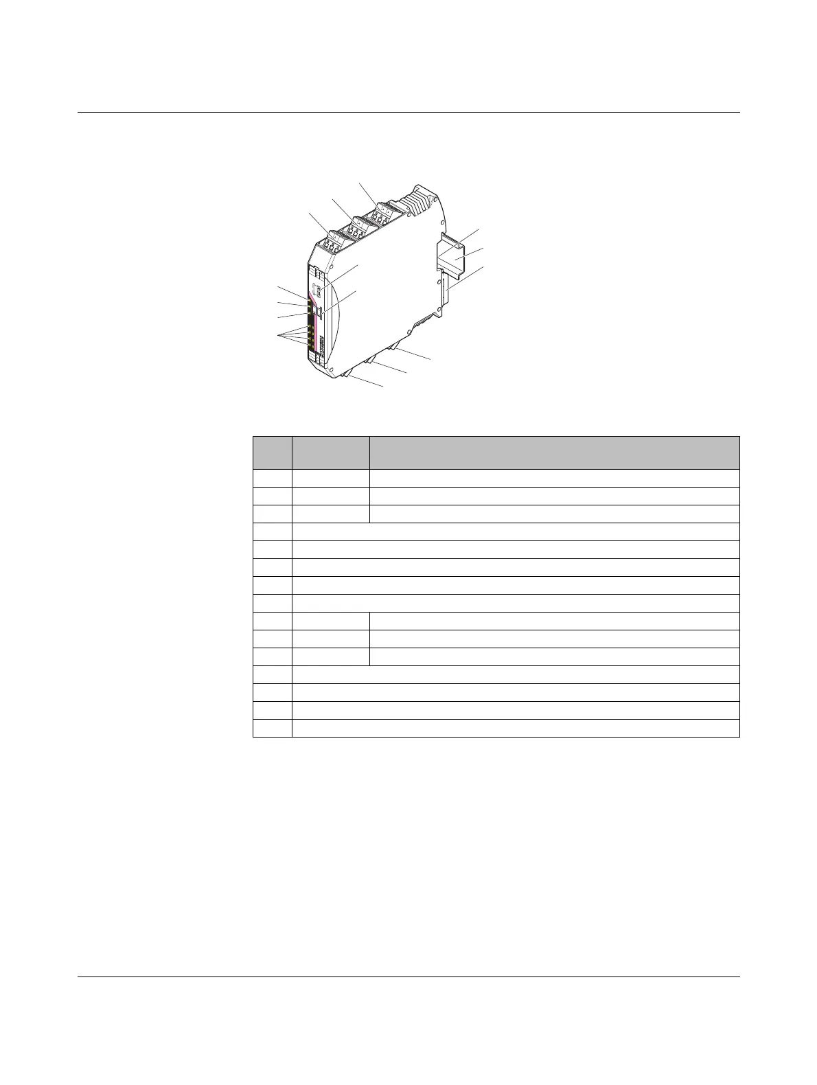
7.7.1 Structure
Figure 7-29 RAD-DO8-IFS structure
Item Ter mi na l
block
Designation
1 3.1/3.2/3.3 Transistor outputs 3 + 4
2 2.1/2.2/2.3 Transistor outputs 1 + 2
3 1.1/1.2/1.3 Supply voltage for outputs 1 ... 4
4 DIP switches for setting the output behavior of the transistor outputs (hold/reset)
5 White thumbwheel for setting the I/O MAP address
6 Connection option for DIN rail connector
7DIN rail
8 Metal foot catch for DIN rail fixing
9 4.1/4.2/4.3 Transistor outputs 5 + 6
10 5.1/5.2/5.3 Transistor outputs 7 + 8
11 6.1/6.2/6.3 Supply voltage for outputs 5 ... 8
12 Status LEDs of transistor outputs DO1 ... DO8
13 ERR status LED, red (communication error)
14 DAT status LED, green (bus communication)
15 PWR status LED, green (supply voltage)
+24V
5-8
DO
7
DO
5
IO-MAP
RAD-DO8-IFS
5
-8
DO
8
DO
6
5-8
5-8
5
-8
P
W
R
DA
T
E
RR
D
O
1
D
O
3
D
O
5
D
O
7
D
O
2
DO
4
DO
6
D
O
8
DO
1
+24V
1
-4
1-4
1
-4
D
O
2
DO
4
1-4
1-4
D
O
3
1
2
3
4
O
FF
O
N
D
IP-1
8
8
D
O
1
+24V
1-4
1-4
1-4
D
O
2
D
O
4
1-4
1
-
4
DO
3
2
3
5
6
8
10
15
14
13
11
7
12
1
9
4

 Loading...