Configuration and startup
105542_en_05 PHOENIX CONTACT 53 / 198
4.9.2 Setting the address of the extension modules via the
thumbwheel
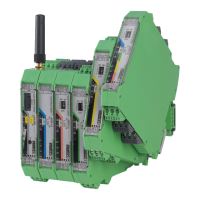
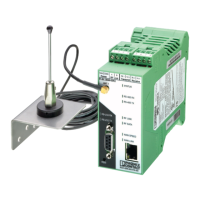
For I/O-to-I/O transmission of signals, you must assign a corresponding output module to
an input module. Set the I/O MAP address (01 ... 99) using the white thumbwheel on the
I/O extension module.
Addressing extension modules
• Use the thumbwheel to set the address.
• Press the SET button on the front of the wireless module to read the active configura-
tion.
The following settings can be made using the white thumbwheel:
The following conditions must be met:
– Addresses 1 ... 99 (maximum) can be assigned for the extension modules in the entire
wireless network.
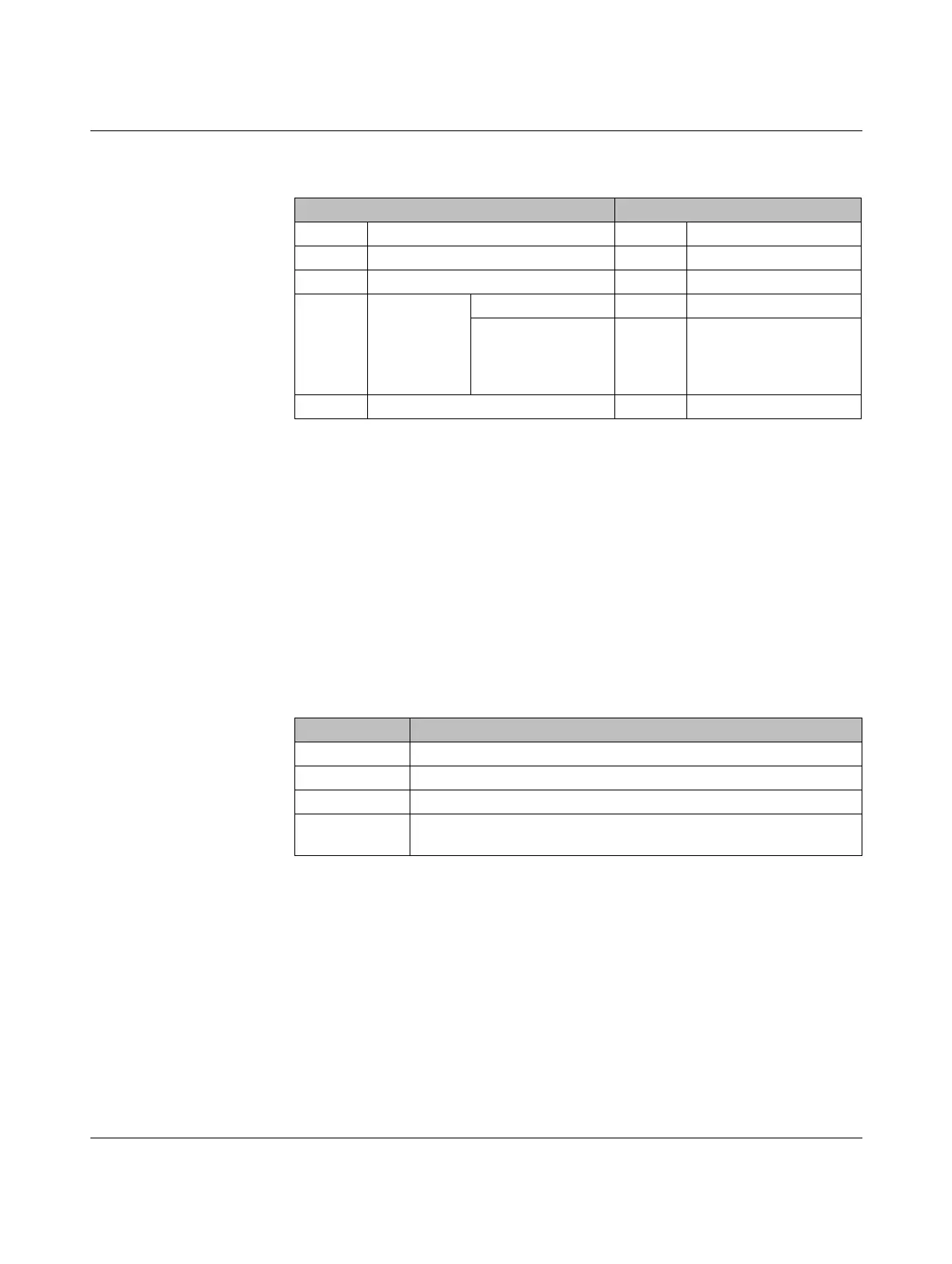
Table 4-9 Assignment of input modules and output modules
Input module Output module
2901537 RAD-AI4-IFS 2901538 RAD-AO4-IFS
2904035 RAD-PT100-4-IFS 2901538 RAD-AO4-IFS
2901535 RAD-DI4-IFS 2901536 RAD-DOR4-IFS
2901539 RAD-DI8-IFS Static mode 2902811 RAD-DO8-IFS
Pulse counter mode - No output module, can
only be used in
PLC / Modbus/RTU mode
or dual mode
2901533 RAD-DAIO6-IFS 2901533 RAD-DAIO6-IFS
Table 4-10 White thumbwheel setting
Thumbwheel Description
01 ... 99 I/O MAP address
00 Delivery state
**, 1* ... 9* Setting not permitted
*1 ... *9 Interface system slave address, for use with other interface system
master devices (IFS)

 Loading...