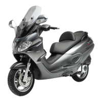
- Insert the pulley on the cam shaft while keeping
the reference 4V in correspondence with the ref-
erence mark on the head.
- Assemble the counterweight with the corre-
sponding fixing screw and tighten to the prescribed
torque.
Locking torques (N*m)
Counterweight screw 7 ÷ 8.5
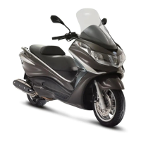
Fit the end-of stroke ring on the valve-lifting mass
and fit the automatic valve-lifting cam to the cam-
shaft.
N.B.
LUBRICATE WITH GREASE THE END-OF-STROKE RING
IN ORDER TO AVOID ACCIDENTAL LEAKS THAT MAY
FALL INTO THE ENGINE. ASSEMBLE THE AUTOMATIC
VALVE-LIFTER RETURN SPRING. DURING THIS OPERA-
TION THE SPRING MUST BE LOADED AT APPROXIMATE-
LY 180°.
Assemble the limiting bell using the counterweight
fixing screw as a reference.
- Tighten the clamping screw to the prescribed tor-
que.
Locking torques (N*m)
Limiting bell screw 11 ÷ 15 Nm
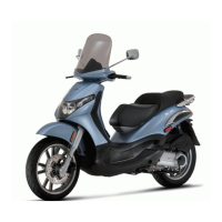
Set the tensioner cursor to the rest position.
- Fit the chain tensioner on the cylinder, using a
new gasket, and tight the two screws to the pre-
scribed torque.
Insert the chain tensioning screw, together with the
spring and washer, tightening it to the prescribed
torque.
Locking torques (N*m)
Tensioner screws 11 ÷ 13 Tensioner cover 5 ÷ 6
Nm
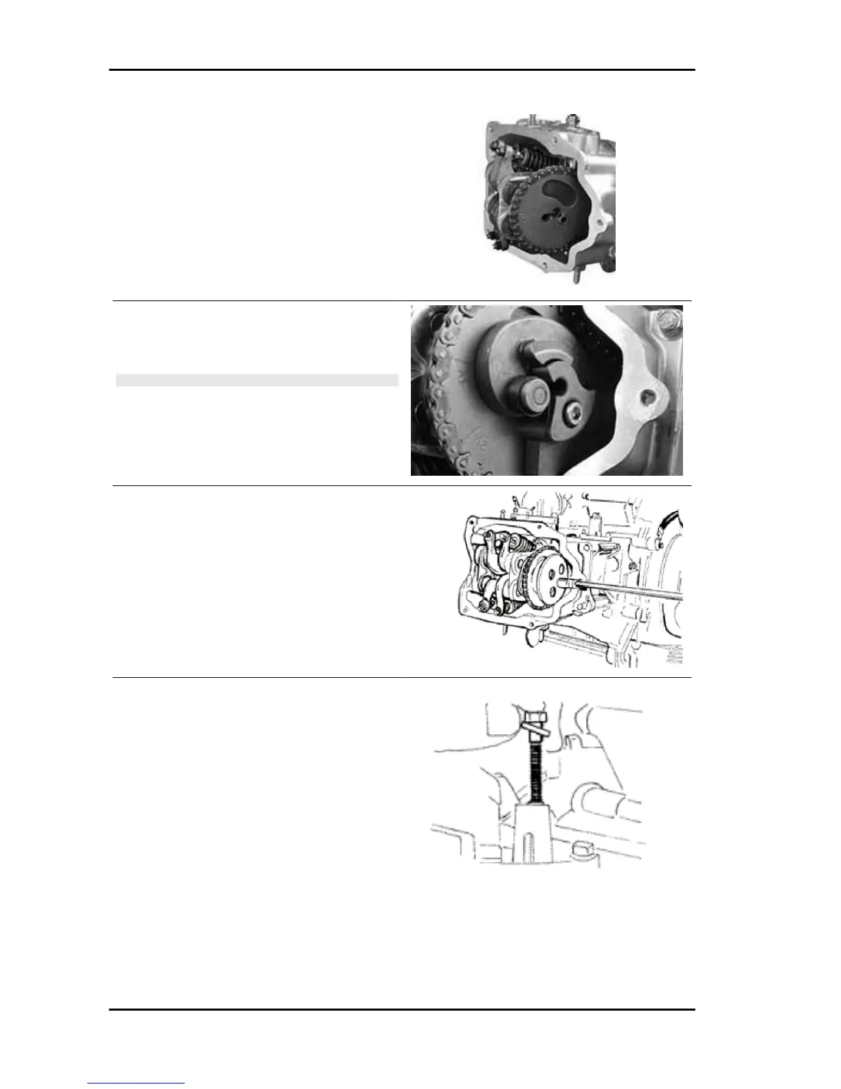
Adjust valve clearance
- Fit the spark plug.
Electrode distance 0.8 mm
Locking torques (N*m)
Engine B 125-250
ENG - 166