Spark plug 12 ÷ 14
Refit the cylinder head cover, tightening the 5 screws to the prescribed torque. Make sure the gasket
is positioned properly.
Remove the flywheel cover completely as already described in the flywheel chapter.
- Reassemble the oil pump control, the chain compartment cover, the by-pass and the oil sump as
described in the lubrication chapter.
- Reassemble the driving pulley, the belt and the transmission cover as described in the transmission
chapter.
Locking torques (N*m)
Tappet cover screws 6 - 7 Nm
TIMING SYSTEM COMPONENTS ASSEMBLY
Name Torque in Nm
Tappet cover screws 6 - 7 Nm
Spark plug 12 ÷ 14
Tensioner cover 5 ÷ 6 Nm
Tensioner screws 11 ÷ 13
Limiting bell screw 11 ÷ 15 Nm
Counterweight screw 7 ÷ 8.5
Plate screws 4 ÷ 6 Nm
Slider screw 10 ÷ 14 Nm
- Fit the timing chain guide pad.
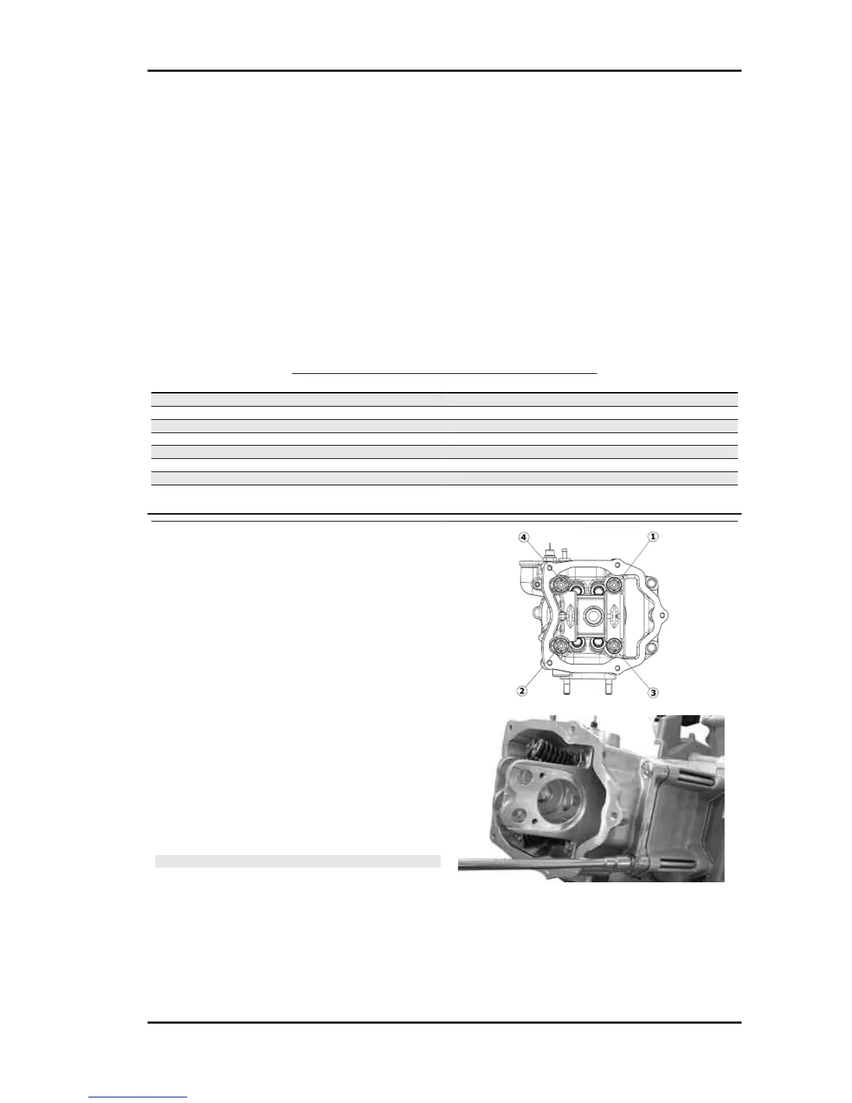
- Insert the centring dowel between the cylinder
head to the cylinder, fit the cylinder head gasket
and the cylinder head.
- Lubricate the stud bolt threading.
- Tighten up the nuts to an initial pre-torque of 7±1
N·m
- Tighten up the nuts to a second pre-torque of 10
±1 N·m
- Rotate by an angle of 270°
- To carry out the operations described above, fol-
low the tightening sequence in the figure.
- Fit the two screws on the outside of the timing
chain side and tighten them to the specified torque.
N.B.
BEFORE INSTALLING THE HEAD, MAKE SURE THAT THE
LUBRICATION CHANNEL IS CLEAN USING A COM-
PRESSED AIR JET.
Locking torques (N*m)
Timing chain tensioner support screw 11 ÷ 13
B 125-250 Engine
ENG - 167