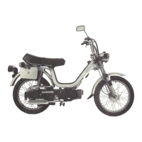
- Couple the crankcases, paying particular atten-
tion to avoid accidental movements during inser-
tion of the crankcase half which could cause
collision with the oil pump control toothing on the
crankshaft and, consequently, damage the bush-
ings.
- insert the crankcase fastening screws and tighten
it them to the specified torque.
Locking torques (N*m)
Engine-crankcase coupling screws 11 ÷ 13
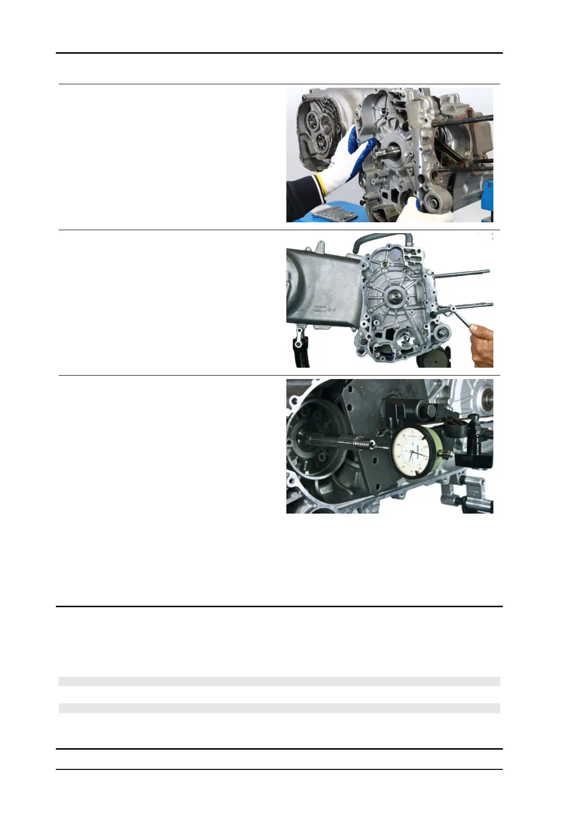
- Complete the coupling operations with the verifi-
cation of the crankshaft axial clearance.
- Using specific tools to support the dial gauge,
verify that the fitting clearance is within the limits.
- Higher clearances are signs of wear of the crank-
shaft - crankcase supporting surfaces.
Specific tooling
020163Y Crankcase splitting plate
020335Y Magnetic mounting for dial gauge
Characteristic
Crankshaft-crankcase axial clearance (H)
0.15 ÷ 0.43 mm
Studs
- Using two nuts, fitted as nut and lock nut type, remove and then drive from the seat.
- Proceed with a thorough cleaning of the threaded seat on the crankcase.
N.B.
THE STUD BOLTS MUST BE REPLACED AT EACH REMOVAL OF THE CYLINDER HEAD.
N.B.
NEW STUD BOLTS DO NOT NEED THREADLOCK, AS THEY COME EQUIPPED WITH SCOTCH-
GRIP.
Engine Beverly 400 E5
ENG - 142