PISTON-CYLINDER COUPLING CATEGORY
Name Initials Cylinder Piston Play on fitting
cylinder - piston M (84.010 ÷ 84.017)mm (83.953 ÷ 83.960)mm (0.050 ÷ 0.064)mm
cylinder - piston N (84.017 ÷ 84.024)mm (83.960 ÷ 83.967)mm (0.050 ÷ 0.064)mm
cylinder - piston O (84.024 ÷ 84.031)mm (83.967 ÷ 83.974)mm (0.050 ÷ 0.064)mm
cylinder - piston P (84.031 ÷ 84.038)mm (83.974 ÷ 83.981)mm (0.050 ÷ 0.064)mm
N.B.
THE PISTON MUST BE INSTALLED WITH THE ARROW FACING TOWARDS THE EXHAUST SIDE,
THE PISTON RINGS MUST BE INSTALLED WITH THE WORD «TOP» OR THE STAMPED MARK
FACING UPWARDS.
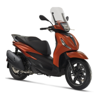
- Check that the head coupling surface is not worn
or misshapen.
- Pistons and cylinders are classified according to
diameter. The coupling is carried out in pairs (M-
M, N-N, O-O, P-P).
Characteristic
Maximum allowable run-out:
0.001 in 0.05 mm
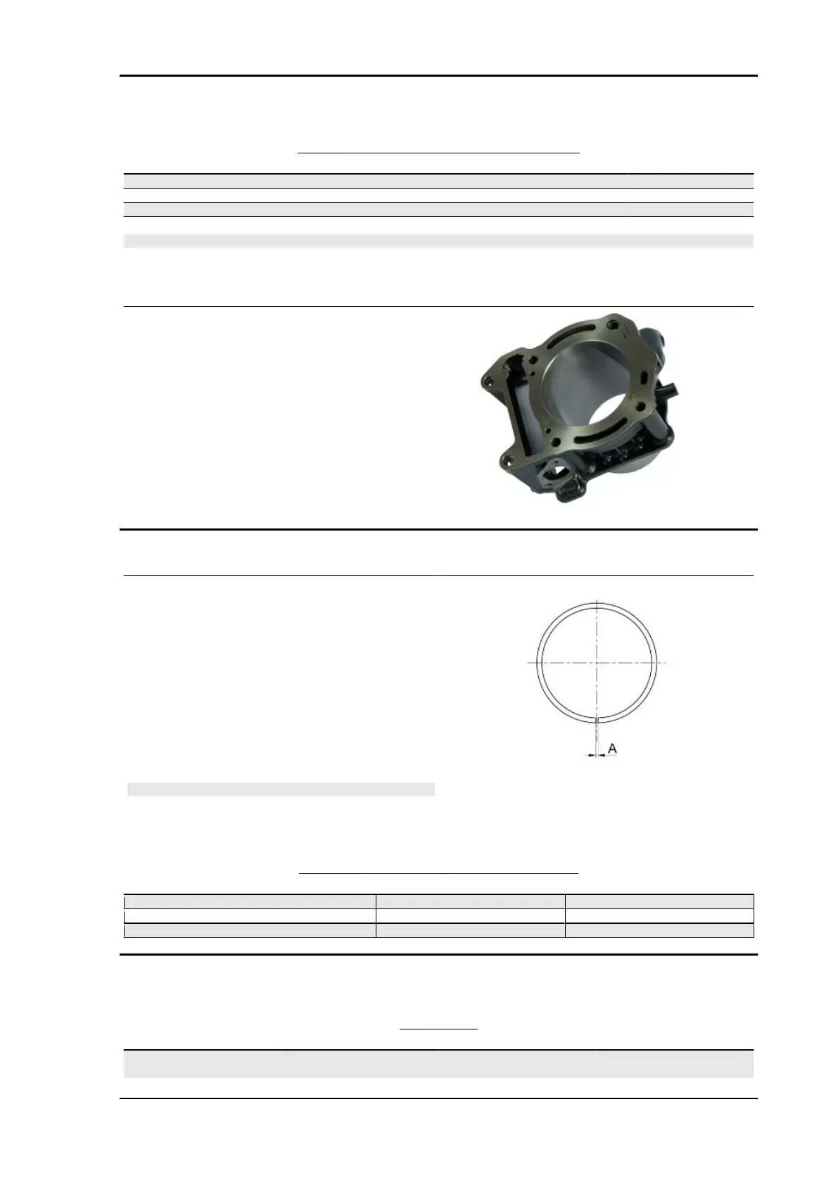
Piston rings
- Carefully clean the seal housings.
- Measure the coupling clearance between the
sealing rings and the piston grooves using suitable
sensors, as shown in the diagram.
- If the clearance is greater than that indicated in
the table, replace the piston.
- Check the clearance upon mounting (A) of the
bands:
N.B.
MEASURE THE CLEARANCE BY INSERTING THE BLADE
OF THE FEELER THICKNESS GAUGE FROM THE SECOND
SEAL SIDE.
ASSEMBLY CLEARANCE OF BANDS - SEAL RINGS
DENOMINATION DIMENSIONS ASSEMBLY CLEARANCES (A)
1st compression ring 84 x 1 mm 0.10 ÷ 0.30 mm
Oil scraper ring 84 x 1.5 mm 0.35 ÷ 0.55 mm
Oil scraper ring 84 x 2.5 mm 0.25 ÷ 0.55 mm
Crankcase - crankshaft - connecting rod
CRANKSHAFT
Titolo Durata/Valore Testo Breve (< 4000 car.) Indirizzo Immagine
Crankshaft Axial clearance between
crankshaft and connecting rod
Beverly 400 E5 Technical Data
DT - 33