Function description
Operating Manual PNOZ m B1
1003790-EN-02
| 14
4.5 Block diagram
4.6 Diagnostics
The status and error messages displayed by the LEDs are saved in an error stack. This er-
ror stack can be shown on the display or can be read from the PNOZmulti Configurator via
the Ethernet interface. More comprehensive diagnostics are possible via the interfaces or
via one of the fieldbus modules. For more information refer to the document PNOZmulti2
Communication Interfaces and the Online Help for the PNOZmulti Configurator.
4.7 Ethernet interface
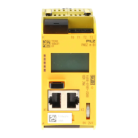
The product PNOZ m B1 has an Ethernet interface to
} Manage and download projects
} Read the diagnostic data
} Set virtual inputs for standard functions
} Read virtual outputs for standard functions.
Information on diagnostics via the interfaces can be found in the document PNOZmulti
Communication Interfaces.
The connection to Ethernet is made via the two 8-pin RJ45 sockets.
The Ethernet interface is configured via the menu in the display (see chapter entitled Dis-
plays and settings) or in the PNOZmulti Configurator (see Online Help for the PNOZmulti
Configurator).

 Loading...