PDP-507CMX
87
5678
56
7
8
C
D
F
A
B
E
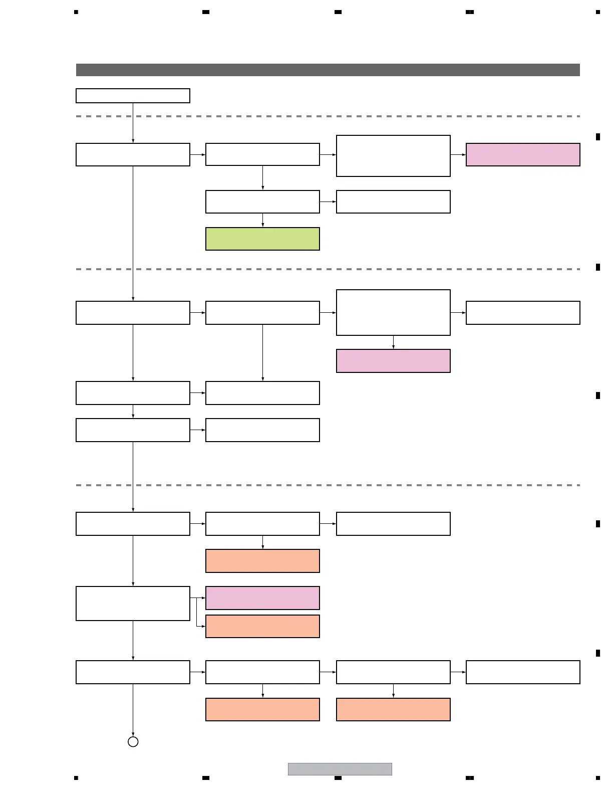
5. DIAGNOSIS INFORMATION
5.1 THE FLOW OF DIAGNOSIS
Flowchart of Failure Analysis for The Whole Unit
START
Is the STB LED lit? Is STB 3.3 V power supplied?
Can the unit be turned on
(Relay ON)?
Is the panel arbitrary turned on or
off repeatedly? Or do luminescent
spots appear on the screen?
Is the power shutdown?
A shutdown occurs.
See "Shutdown diagnosis." ⇒ SD
Is the voltage at AC_DET on the
POWER SUPPLY Unit high?
Replace the POWER SUPPLY
Unit.
A power-down will not be generated if the drive is off.
• Check the DRF SW.
• Before turning the drive off with the RS-232C
commands or using the remote control unit,
turn the unit off.
In a case where luminescent spots appear
or the panel is repeatedly turned on or off
In a case where luminescent spots appear
Is the voltage at the RELAY port
of the connectors between the
DIGITAL and POWER SUPPLY
Assys H (3.3 V)?
No
No
Is the drive off?
Turn the drive on.
Is the abnormality associated
with a single scan line?
No
Yes
Yes
Yes
Yes
A power-down occurs.
Does the screen display reset
lighting?
Is there any local abnormality
on the screen?
Is the abnormality associated
with one address or one TCP?
See "Power-down diagnosis." ⇒ PD
Yes
No
No
No
Yes
No
No
NG
No
Yes
Yes
Yes
Yes
No
No
Yes
No
Yes
Yes
No
Yes
Problems concerning STB status
Problems concerning the power
Problems concerning lighting of the panel
Failure analysis for the
MAIN Assy. ⇒ ST1
Replace the MAIN Assy.
Failure analysis for the
POWER SUPPLY Unit. ⇒ PS1
Failure analysis for the
POWER SUPPLY Unit. ⇒ PS2
Failure analysis for the
POWER SUPPLY Unit. ⇒ PS3
Failure analysis for the
drive system ⇒ DR1
Failure analysis for the
drive system ⇒ DR2
Failure analysis for the
drive system ⇒ DR3
Failure analysis for the
drive system ⇒ DR4
Yes
No
Replace the panel chassis.
A
Check if the cable between
CN304 and P12 that connects the
POWER SUPPLY and DD Assys
is firmly connected.
As to the diagnosis of DD Assy, refer to "Flowchart of Failure Analysis for the DD Assy".
As to the diagnosis of SLOT power supply, refer to "Flowchart of Failure Analysis for the SLOT Powwer Supply".

 Loading...