PDP-507CMX
144
1234
1234
C
D
F
A
B
E
7.5 ADJUSTMENTS WHEN THE DRIVE ASSYS ARE REPLACED
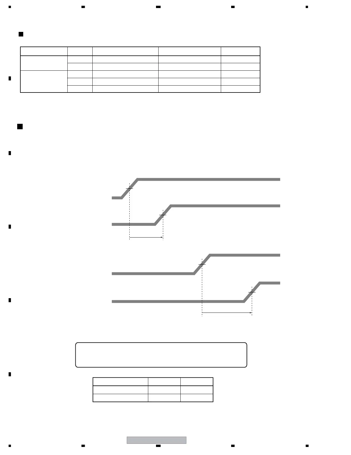
TIME LAG ADJUSTMENT OF THE CONTROL SIGNAL (SUS-B)
1 Measure the time lag for the SUS-U signal to the SUS-B signal.
2 Check the time lag for the SUS-B GATE signal to the SUS-U GATE siganl.
Adjust the variable control so that the time lag of GATE becomes " time lag of input signal + α ± 5 nsec."
Note: For details on measuring points of waveform, see the figure below.
50 % of the crest value
50 % of the crest value
50 % of the crest value
time lag of SUS-U gate and SUS-B gate : ∆ Tsus-gub
Adjust so that "∆ Tsus-gub = ∆ Tsus-iub + α ± 5 nsec," using the variable
controls shown in the table below:
SUS-U signal (input to the DRIVE Assy)
SUS-B signal (input to the DRIVE Assy)
SUS-U signal (input to the DK module)
SUS-B GATE signal
50X MAIN DRIVE (GATE signal of Q1210)
50Y MAIN DRIVE (GATE terminal of Q2210)
50 % of the crest value
time lag of SUS-U and SUS-B
∆ Tsus-iub
time lag of SUS-U GATE and SUS-B GATE
∆ Tsus-gub
Assy VR Value of α
50X MAIN DRIVE ASSY
VR1001 70 nsec
50Y MAIN DRIVE ASSY
VR2001 50 nsec
Waveform adjustments required when replacing the following parts of the 50X MAIN DRIVE and
50Y MAIN DRIVE Assys.
Assy Name Ref No. Part Name Part Category Remarks
50X MAIN DRIVE Assy
IC1205 PS9117P Photo Coupler
IC1204 TND307TD FET Driver
50Y MAIN DRIVE Assy
IC2104 TND307TD FET Driver
IC2209 PS9117P Photo Coupler
IC2208 TND307TD FET Driver
 Loading...