c. Inspect
all control
switches and
the ignition switch, to determine their
condition. Connect a jumper lead a-
round any switch suspected of being de-
fective. If the system functions prop-
erly using this method, repair or re-
place the
bypassed
switch.
d. If specified battery voltage can be
measured at the motor terminal of the
cranking motor, allowing for some
voltage drop in the circuit and the engine
is known to be
functioning properly,
re-
move the motor
and follow the test
pro-
cedures.
PIPER CHEROKEE
SIX SERVICE
MANUAL
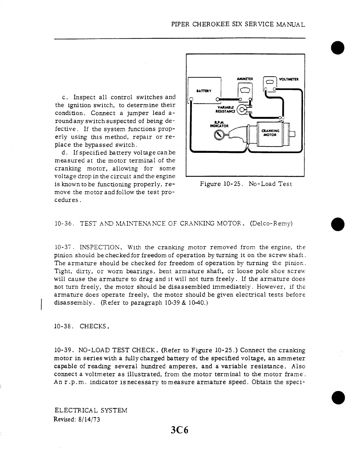
Figure
10-25.
No-Load Test
10-36. TEST AND MAINTENANCE OF CRANKING MOTOR. (Delco-Remy)
10-37.
INSPECTION. With the cranking
motor removed from the engine,
the
pinion should be checked for freedom of operation by turning it on the screw shaft.
The armature should be checked for freedom of operation by turning the pinion.
Tight, dirty, or worn bearings, bent armature shaft, or loose pole shoe screw
will cause the armature to drag and it will not turn freely. If the armature does
not turn freely, the motor
should be disassembled immediately.
However, if the
armature does operate freely, the motor should be given electrical tests before
disassembly. (Refer to paragraph 10-39 & 1040.)
10-38. CHECKS.
10-39. NO-LOAD
TEST CHECK.
(Refer to Figure
10-25.) Connect
the cranking
motor in series with a fully charged battery of the specified voltage, an ammeter
capable of reading several hundred amperes, and a variable resistance. Also
connect a voltmeter as illustrated, from the motor terminal to the motor frame.
An r.p.m. indicator is necessary tomeasure armature speed. Obtain the speci-
ELECTRICAL SYSTEM
Revised:
8/14/73
3C6