EasyManuals Logo

Piper PA-32RT-300T User Manual

Piper PA-32RT-300T
568 pages
To Next Page IconTo Next Page
To Previous Page IconTo Previous Page
Page #547 background imageLoading...
Page #547 background image
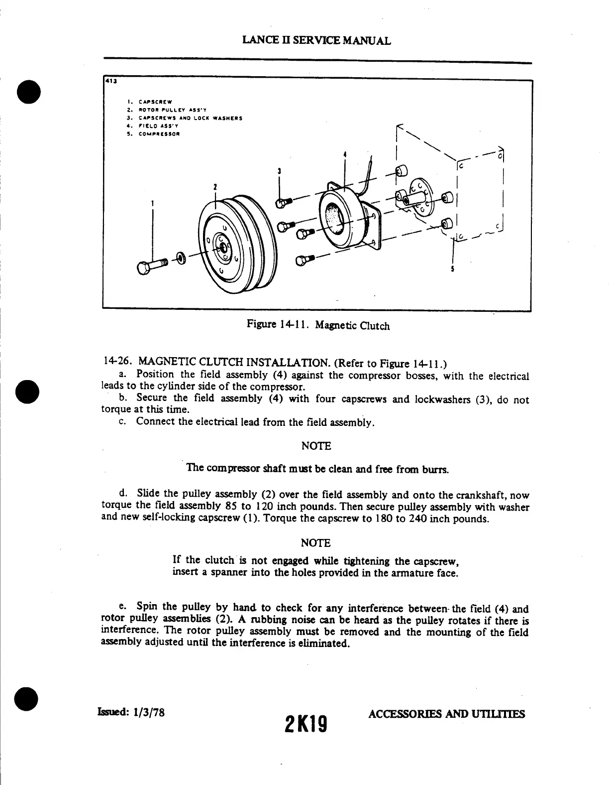
413
1.
CAPSCREW
2. ROTOR
PULLEY ASS'Y
3.
CAPSCREWS
AND
LOCK
WASHERS
4.
FIELD
ASS'Y
5.
COMPRESSOR
Figure
14-11.
Magnetic
Clutch
14-26.
MAGNETIC
CLUTCH
INSTALLATION.
(Refer
to
Figure
14-11.)
a.
Position
the
field
assembly
(4)
against
the
compressor
bosses,
with
the
electrical
leads
to
the
cylinder
side
of
the
compressor.
b.
Secure
the
field
assembly
(4)
with
four
capscrews
and
lockwashers
(3),
do
not
torque
at
this
time.
c.
Connect
the
electrical
lead
from
the
field
assembly.
NOTE
The
compressor
shaft
must
be
clean
and
free
from
burrs.
d.
Slide
the
pulley
assembly
(2)
over
the
field
assembly
and
onto
the
crankshaft,
now
torque
the
field
assembly
85
to
120
inch
pounds.
Then
secure
pulley
assembly
with
washer
and
new
self-locking
capscrew
(1).
Torque
the
capscrew
to
180
to
240
inch
pounds.
NOTE
If
the
clutch
is
not
engaged
while
tightening
the
capscrew,
insert
a
spanner
into
the
holes
provided
in the
armature
face.
e.
Spin
the
pulley
by
hand
to
check
for
any
interference
between-the
field
(4)
and
rotor
pulley
assemblies
(2).
A
rubbing
noise
can
be
heard
as
the
pulley
rotates
if
there
is
interference.
The
rotor
pulley
assembly
must
be
removed
and
the
mounting
of
the
field
assembly
adjusted
until
the
interference
is
eliminated.
Issued:
1/3/78
ACCESSORIES
AND
UTILITIES
2K19
LANCE
II
SERVICE
MANUAL

Table of Contents

Questions and Answers:

Question and Answer IconNeed help?

Do you have a question about the Piper PA-32RT-300T and is the answer not in the manual?

Piper PA-32RT-300T Specifications

General IconGeneral
BrandPiper
ModelPA-32RT-300T
CategoryAircrafts
LanguageEnglish

Related product manuals