ENGLISH
27
33 / 15 /
K
R
W
W
P
R
W
Y
R
Y
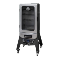
K(Black)
W(White)
R(Red)
Y(Yellow)
P(Purple)
O(Orange)
G(Green)
K
The Digital Control Board system is an intricate and valuable piece of technology. For protection from power surges and electrical
shorts, consult the wire diagram below to ensure your power source is sufficient for the operation of the unit.
110120, 60z, 250, 3
: Electrical components, passed by product safety testing and certification services, comply
with a testing tolerance of ± 5-10 percent.
/
120, 200,
0375” 5000” / 95 127
120, 60z,
1
120, 60z,
2
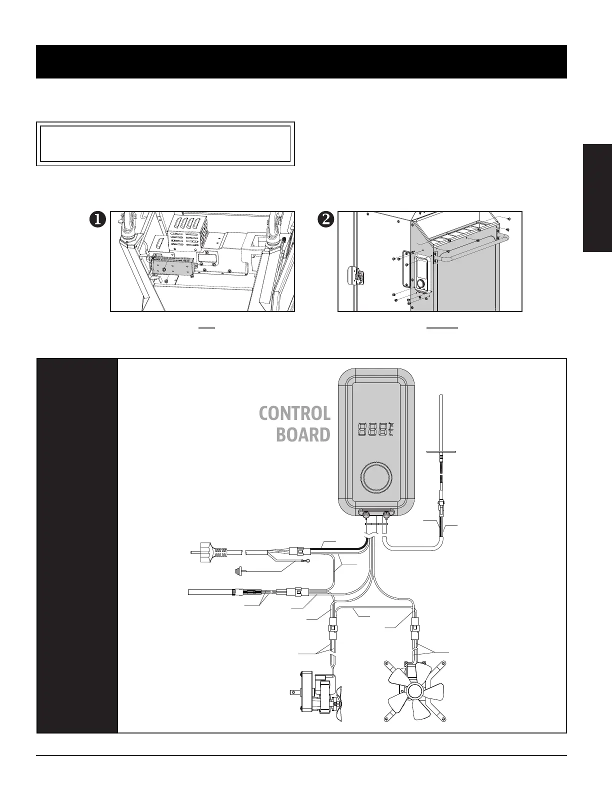
Locte nd remove the four screws of the
electrc wre sheld on undersde of unt
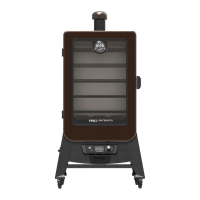
Locte nd remove the thrteen screws
tht secure the hopper