4-4 SV61831 Rev. A DA50S/DA55S/DA70S/DA75S AddressRight™ Printers Service Manual
4 • Troubleshooting/Diagnostics
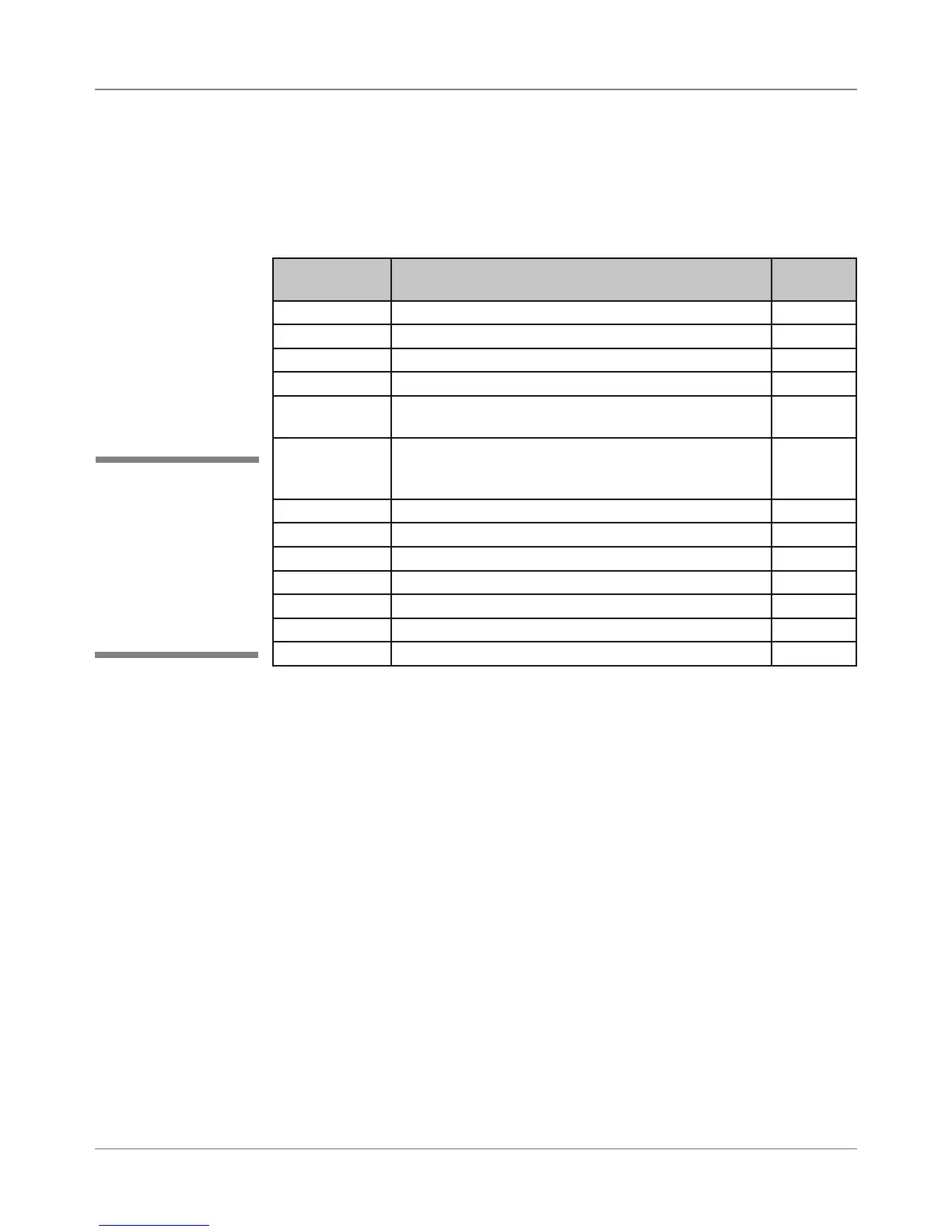
Main Controller Board Voltage Checks
To help your troubleshooting, measure the voltages on the Main Controller
Board (with power applied) using a digital voltmeter (see tables below).
Voltage With
Normal Range
Where It Comes From/Going Location
1.5V ±5% Generated from main board TP32
3.3V ±5% Generated from main board TP31
5V ±5% Generated from main board TP54
6.5V ±5% Input from power supply TP57
12V ±5% Generated from main board (voltage occurs during
printing or when stopped)
TP56
15V ±5% Generated from main board (voltage occurs when
print heads are moving into maintenance station;
maintenance motor is running)
TP56
40V ±5% Input from power supply TP55
16V ±1.5V Generated from main board (U20) for Transport Motor U20, pin 1
13V ±1.5V Generated from main board (U24) for Shuttle Motor U24, pin 9
Ground Ground for 3.3V measurement TP29
Ground Ground for 1.5V measurement TP30
Ground Ground for 12V, 15V, 40V measurement TP52
Ground Ground for 5V, 6.5V measurement TP53
Table 4-1 Main Board Test Points With Voltage Ranges
4.2 Main
Controller
Board
Diagnostics
✍
TIP: Device name
is unique to each
printer’s main board.
Therefore, replacing
an existing main board
in the printer gives that
printer a new device
name.