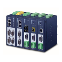
User’s Manual of IMG-110T
-70-
APPENDIX A
A.1 Device‘s RJ45 Pin Assignments
■ 10/100Mbps, 10/100BASE-TX
Contact MDI MDI-X
Implicit implementation of the crossover function within a twisted-pair cable, or at a wiring panel, while not expressly
forbidden, is beyond the scope of this standard.
A.2 RJ45 cable pin assignment
There are 8 wires on a standard UTP/STP cable and each wire is color-coded. The following shows the pin allocation and
color of straight cable and crossover cable connection:
Straight Cable SIDE 1 SIDE 2
1 2 3 4 5 6 7 8
1 2 3 4 5 6 7 8
SIDE 1
1 = White / Orange
2 = Orange
3 = White / Green
4 = Blue
5 = White / Blue
6 = Green
7 = White / Brown
8 = Brown
1 = White / Orange
2 = Orange
3 = White / Green
4 = Blue
5 = White / Blue
6 = Green
7 = White / Brown
8 = Brown
SIDE 2
Straight Cable SIDE 1 SIDE 2
1 2 3 4 5 6 7 8
1 2 3 4 5 6 7 8
SIDE 1
1 = White / Orange
2 = Orange
3 = White / Green
4 = Blue
5 = White / Blue
6 = Green
7 = White / Brown
8 = Brown
1 = White / Orange
2 = Green
3 = White / Orange
4 = Blue
5 = White / Blue
6 = Orange
7 = White / Brown
8 = Brown
SIDE 2
Figure A-1: Straight-through and Crossover Cable
Please make sure your connected cables are with same pin assignment and color as the above diagram before deploying the
cables into your network.
 Loading...