OPERATION & MAINTENANCE MANUAL TMS2000/3000
TMS Operations and Maintenance Manual.docx February 12, 2018
PAGE 15
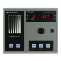
POWER-UP SEQUENCE: Upon application of AC power, the TMS performs a series of tasks prior to normal
operation. These include in the following sequence:
1) A self-test to verify integrity of both system program and data memories, system I/O, and data acquisition
interface electronics. Display is blank during this process.
2) Retrieval and verification of configuration and set-up data.
Display shows
3) System initialization, including reasonableness checking of user-entered configuration data, and pre-startup
calculations.
Display shows
4) Visual display and audible alarm check.
Display shows
with all LEDs on, audible alarm beeps twice.
5) Begin normal operation, display any error messages. For a description of system error, warning, and info
messages, refer to Appendix A.
NOTE: In cases where TMS power has been turned off for more than one to two minutes, a power-up sequence will
generate the following warning message on the display and a similar message on the optional front panel printer:
Warning 21, Power Failure
This message is normal, and is just informing the user that the TMS has recovered from a power failure of at least
1-2 minutes in duration. This may be acknowledged by holding MODE until the TMS beeps once WHILE the message
is displayed.