Do you have a question about the Pneumercator TMS2000 and is the answer not in the manual?
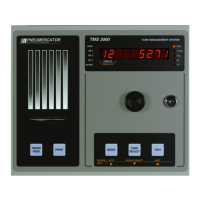
Describes the TMS front panel, its configurations, and components like display, alarms, and pushbuttons.
Details the nine-digit LED display, its alphanumeric capabilities, and annunciator LEDs for alarms and units.
Explains the front panel horn, its silencing options, and how beep rates vary with alarm types.
Outlines the tasks the TMS performs upon AC power application, including self-tests and initialization.
Explains the three user-selectable modes (View, Test, Access) and presents the system's function tree.
Details the View mode, its display formatting, pushbuttons (MODE, TANK SELECT), and printing functions.
Describes entering and operating in Access mode, including review, edit, and print functions for logs and configuration.
Details the scheduled inventory snapshot log, its capacity, record identification, and captured data fields.
Describes the delivery transaction log, its capacity, record identification, and captured data for product delivery.
Explains the optional bulk sales transaction log, its capacity, record identification, and captured data for sales.
Details the theft transaction log, its capacity, record identification, and captured data for unauthorized product withdrawal.
Describes the on-demand product reordering report, its purpose, and captured data for estimating usable product remaining.
Explains the bottom water removal transaction log, its capacity, record identification, and captured data for water withdrawal.
Details the In-Tank Leak Test results showing hourly changes, settings, and captured data for the test.
Summarizes In-Tank Leak Test results, storing the latest passing test for 14 months, and its capacity.
Contains Date/Time of latest Pass/Fail for LS300 Line Leak Rates, supported by an external console.
Records all alarm conditions detected by the TMS, including High/Low liquid and detected Leaks.
Contains system errors representing hardware problems, including probes, sensors, and cabling, also non-alarm warnings.
Defines test length options and EPA approved test lengths based on tank size and leak rate.
Allows selection of an appropriate start time for timed and timed-relay in-tank leak tests.
Specifies the schedule type (Timed, Timed-Relay) for in-tank leak tests.
Defines the frequency of timed and timed-relay tests.
Specifies the day of the week for timed and timed-relay in-tank leak tests.
Allows selection of in-tank leak test control functions like Stop and Start.
Covers general system settings, access codes, security, unit IDs, and site IDs.
Configures tank-specific settings like geometry, setpoints, tank name, type, and capacity.
Provides probe-specific settings for calibration, type, length, and offsets.
Assigns relays to tank channel specific conditions for alarms and signal outputs.
Assigns relays to individual non-hazardous contact closure (CC) inputs.
Assigns relays to individual leak/point level sensor inputs.
Assigns relays to external LS300 Line Leak failures.
Assigns relays to site-specific conditions like theft or power failure.
Defines relay behavior, normal contact state, and delay settings.
Configures non-hazardous contact closure (CC) inputs for various applications.
Configures sensor inputs for alarm purposes or to control TMS functions like relay outputs.
Schedules inventory snapshots per day for up to three times a day, seven days a week.
Defines site hours of operation for theft detection and product loss during closed hours.
Enables and configures optional modem or serial C communication interfaces.
Sets up auto-dialing for alarms and inventory updates, including phone numbers and line types.
Configures In-Tank Leak Test settings, prerequisites, and test modes.
Enables analog output channels to represent tank channel data like volume, level, or temperature.
Sets the system date, including month, day, and year.
Sets the system time in 24-hour format.
Sets the current day of the week.
Initializes or erases memory sections, restoring factory defaults or eliminating corruption.
Provides instructions for replacing the printer ribbon.
Details how to replace the paper roll in receipt printers without a winder.
Provides instructions for replacing the paper roll in receipt printers with a winder.
Describes alarm conditions, their logging, printing, and auto-dial behavior.
Details error conditions, their recording in the event log, and display messages.
Explains warning conditions, their printing, audible/visual alarms, and acknowledgment.
Conveys advisory messages appearing on the TMS display, not logged or producing alarms.
Lists maintenance checks for TMS/LC2000 systems, including printer, display, and horn verification.
Details checks for TMS systems: stick readings, leak test results, and schedule verification.
Describes probe inspection for damage and residue buildup.
Instructions for inspecting and testing ES825 sensors (non-discriminating and discriminating).
Maintenance for float switch sensors, including inspection and float manipulation.
Refer to sensor documentation for HS100/HS100D/HS100ND testing procedures.
Verifying remote alarm/display operation using the Test button and simulating alarms.
Describes the function of each of the four dip switches for system error handling and security.
Procedure step: Enter CONFIG/PROBE or TANK/PROBE submenu.
Procedure step: Enter Probe Length as the transmitter span.
Procedure step: Set Product Height Offset to +0.0.
Procedure step: Repeat for all tanks and save configuration.
Procedure step: Record actual tank levels using a dip stick.
Procedure step: Select VIEW mode and set to product level.
Procedure step: Record the difference between actual and displayed level readings.
Procedure step: Enter CONFIG/PROBE menu or TANK/PROBE submenu.
Procedure step: Set Product Height Offset to the recorded difference.
Procedure step: Repeat for all tanks and save configuration.
Procedure step: Confirm calibration by checking level readings with 4ma and 20ma signals.
Procedure step: Use XMTR SEL to select level transmitter and advance to next.
Procedure step: Position float to 'empty', press ZERO, and check LED.
Procedure step: Position float to 'full', press SPAN, and check LED.
Procedure step: Repeat calibration for all desired transmitters.
Details warranty terms, coverage, conditions, and exclusions for TMS Series products.
| Brand | Pneumercator |
|---|---|
| Model | TMS2000 |
| Category | Control Panel |
| Language | English |