OPERATION & MAINTENANCE MANUAL TMS2000/3000
TMS Operations and Maintenance Manual.docx February 12, 2018
Note: Refer to the model-specific INSTALLATION MANUAL for complete installation details.
Page
Section 1 SYSTEM OVERVIEW
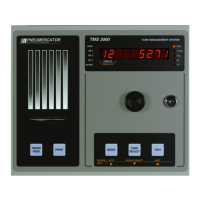
1.1 Front Panel Description .................................................................................................................... 5
1.2 Display .............................................................................................................................................. 6
1.3 Audible Annunciator .......................................................................................................................... 6
Section 2 OPERATION
2.1 Power-Up Sequence ......................................................................................................................... 7
2.2 Overview of Operating Modes/System Function Tree ...................................................................... 8
2.3 View Mode Details ............................................................................................................................ 9
2.4 Access Mode .................................................................................................................................. 11
2.4.1 Logs ................................................................................................................................................ 16
2.4.1.1 Shift Inventory .......................................................................................................................... 17
2.4.1.2 Delivery .................................................................................................................................... 18
2.4.1.3 Bulk Sales ................................................................................................................................ 19
2.4.1.4 Thefts ....................................................................................................................................... 20
2.4.1.5 Product Reordering Report ...................................................................................................... 21
2.4.1.6 Bottom Water Removal ............................................................................................................ 22
2.4.1.7 In-Tank Leak Test Results – Detailed ...................................................................................... 23
2.4.1.8 In-Tank Leak Test Results – History ........................................................................................ 24
2.4.1.9 LS300 Line Leak Test Results ................................................................................................. 25
2.4.1.10 Alarms ...................................................................................................................................... 26
2.4.1.11 Events ...................................................................................................................................... 27
2.4.2 In-Tank Leak Test Scheduling ........................................................................................................ 29
2.4.3 Configuration ................................................................................................................................... 33
2.4.3.1 Header ..................................................................................................................................... 34
2.4.3.2 Tank ......................................................................................................................................... 38
2.4.3.3 Probe ........................................................................................................................................ 45
2.4.3.4 Relay Outputs – Tank/Probe Triggers ...................................................................................... 48
2.4.3.5 Relay Outputs – Contact Closure Input Triggers ..................................................................... 49
2.4.3.6 Relay Outputs – Leak/Point Level Sensors (ISCC) Triggers ................................................... 50
2.4.3.7 Relay Outputs – LS300 Line Leak Test Failure Triggers ......................................................... 51
2.4.3.8 Relay Outputs – Site-Specific Triggers .................................................................................... 52
2.4.3.9 Relay Mode .............................................................................................................................. 53
2.4.3.10 Contact Closure Inputs ............................................................................................................. 55
2.4.3.11 Leak/Point Level Sensor (ISCC) Inputs ................................................................................... 57
2.4.3.12 Inventory .................................................................................................................................. 59
2.4.3.13 Theft ......................................................................................................................................... 61
2.4.3.14 Modem ..................................................................................................................................... 62
2.4.3.15 Dial-Out .................................................................................................................................... 64
2.4.3.16 In-Tank Leak Test Configuration .............................................................................................. 66
2.4.3.17 Analog Outputs ........................................................................................................................ 69
2.4.4 Clock (Date/Time) ........................................................................................................................... 70
2.4.5 Initialize Data .................................................................................................................................. 71
Section 3 PRINTER SERVICING
3.1 Ribbon Replacement (900438-x, Impact Printer) ............................................................................ 72
3.2 Paper Replacement (900438-1, Receipt-Style Impact Printer) ....................................................... 72
3.3 Paper Replacement (900438-2, Autowinder Impact Printer) .......................................................... 73
Appendix A DESCRIPTION OF SYSTEM MESSAGES (ALARMS/EVENTS/WARNINGS) .............................. 74
Appendix B MAINTENANCE .............................................................................................................................. 78
Appendix C DIP SWITCH SETTINGS (900430-1/900461-x) ............................................................................. 80
Appendix D TMS2000A1x 4-20ma Calibration Procedure ................................................................................. 81
Appendix E TMS2000A2x 2-412 and 2-501 Calibration Procedure ................................................................... 82