OPERATION MANUAL TMS4000
TMS4000 Operation Manual 2018-08-03.docx August 3, 2018
PAGE 5
SECTION 1 – PRODUCT DESCRIPTIONS
1.1 GENERAL SYSTEM OVERVIEW
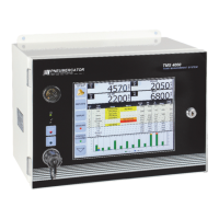
This document covers the operation of the TMS4000 using the touch screen interface. A few
additional details are visible on the face of the TMS4000 as shown below. Below the integrated horn
in the top left corner are three LEDs. From top to bottom, these are the Green Power LED, Green
Normal Status LED, and Red Alarm Status LED. The Alarm Status LED will blink for new alarms.
Once the TMS alarm has been acknowledged using the Acknowledge button (Bell icon) in the top
corner of the touch screen, the Alarm Status LED will not blink and will stay on until the alarm condition
is satisfied. Once the alarm condition is satisfied, the Alarm Status LED will be off and the Normal
Status LED will be on. Below the LEDs is the Day/Night sensor used to detect the ambient light and
automatically adjust the screen brightness, when enabled.
The touch screen is the primary interface for viewing real-time status of tank probes, sensors, and
contact closure inputs. Additional access is provided for viewing system reports, changing the system
Configuration, and upgrading the TMS firmware.
This manual was written referencing TMS4000 firmware version 10.044. Although some screen
shots may vary between firmware versions, the principle of operation remains the same. Contact
Pneumercator for any firmware version specific questions.