Apply Marine Grade
Silicone Sealant PN
8560054
Final Drive / Propulsion
5.21
Pum p Alignm ent
NOTE: Checking the pump alignment is not required if the alignment is not suspect. You need only to verify align-
ment if alignment is determined to be incorrect. Symptoms of incorrect pump alignment are, but not limited to:
stripped driveshaft, stripped coupler splines, broken engine mounts, and unevenly worn driveshaft, and worn
bearing carriers.
1. If pump housing was removed, begin by re--attaching
to the hull. Refer to pages: 5.3 and 5.4 for bolt torque.
2. Disconnect lanyard cord lock plate from engine stop
switch. Remove battery negative cable.
3. Remove impeller and stub shaft from pump housing.
Inspect bearings for wear or damage and replace if
necessary. See Stator Disassembly/Inspection this
section.
4. Assemble pump without stub shaft, impeller, or tail
cone.
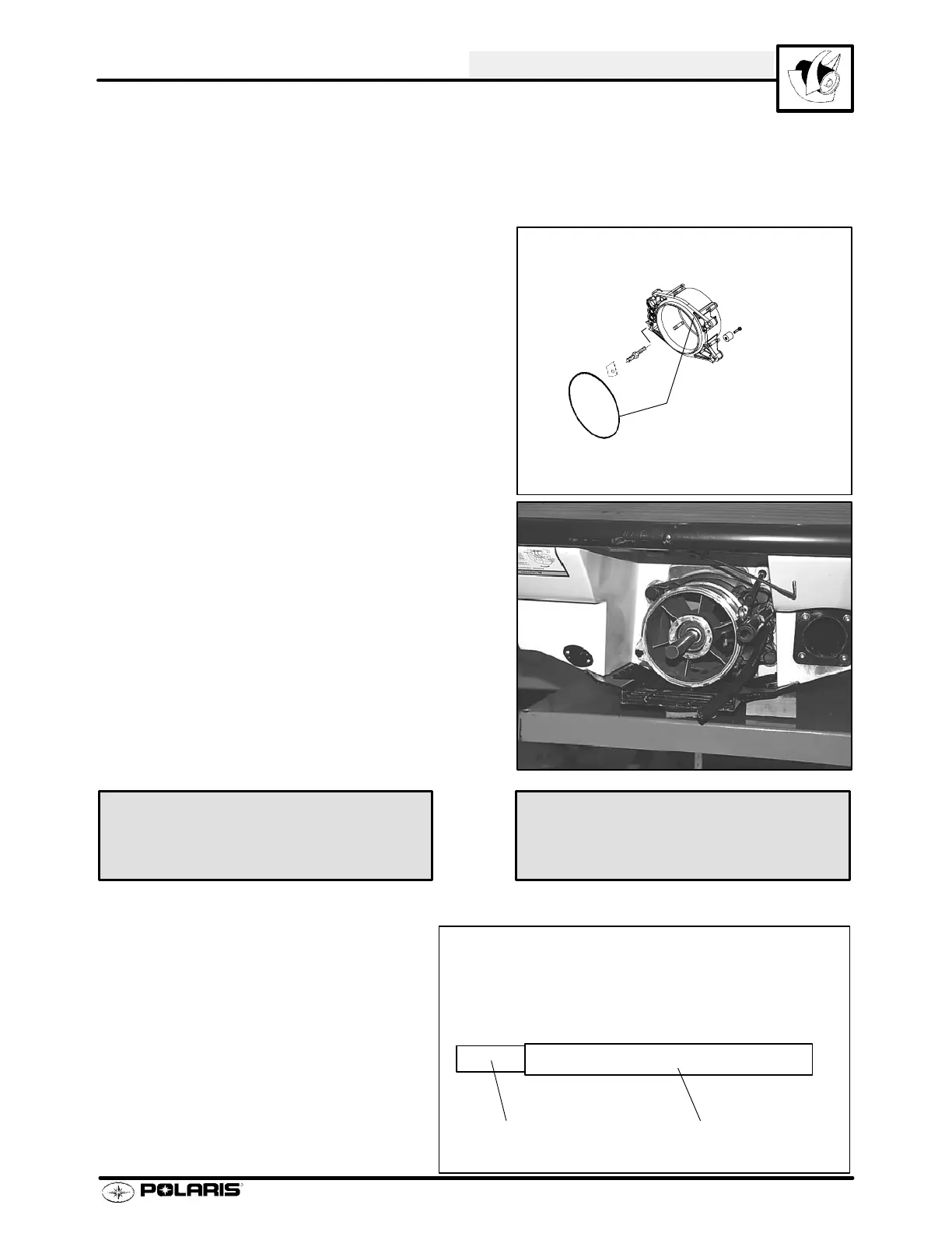
5. Install stator housing to pump housing. Tighten
mounting bolts to 18 ft. lbs. (24.8 Nm).
6. Install alignment tool into pump bearing housing with the smaller diameter coupler end facing toward engine.
7. Slide coupler end of alignment tool into
drive coupler.
8. If engine and pump are properly aligned,
the tool will slide freely into the engine
coupler .
9. If mis-alignment is evident, determine the
probable cause of misalignment from the
following chart and correct the condition.
Alignment Tool PN 2871343
Stator Housing Mounting Bolt
Torque -- 18 ft. lbs. (24.8 Nm)
W atercraft Engine/Pump Alignment Tool PN 2871343
Coupler end -
small diameter
Pump end -
large diameter
 Loading...