Electrical Systems
7.29
Trigger Coil Testing -- Generation III PVL Ignition Systems
NOTE: The BLUE wire is found only on 1200cc engines. 700cc engines will only have a GREEN and RED
wire.
S All 2001 Carbureted (700cc and 1200cc)
The trigger coils are Hall Effect sensors and re-
quire a constant DC power source via the brown
wire out of the CDI module. The wire is powered
when the engine is cranked for starting and while
running. When a magnet (sealed in the magnet
holder on the flywheel) is passed by the sensor , the
sensor becomes conductive and triggers the re-
lease of the energy stored in the capacitor, creat-
ing the ignition spark.
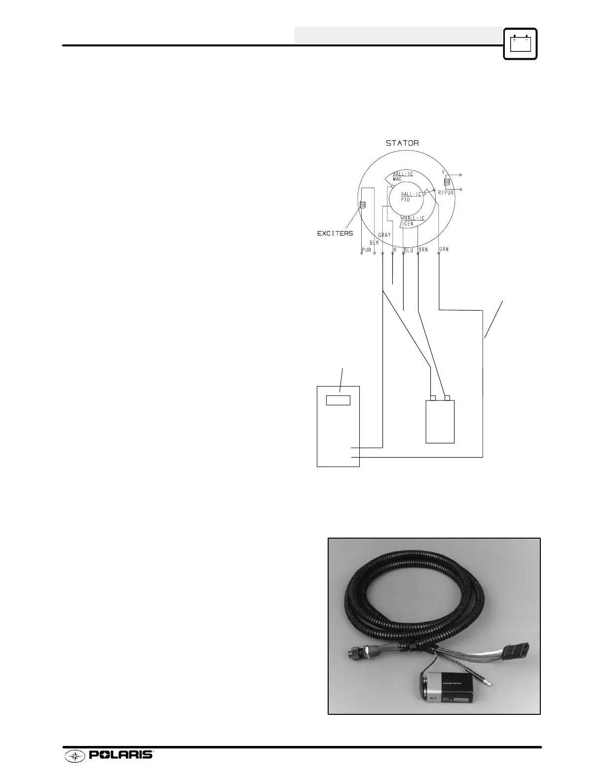
1. To test trigger coils, disconnect the stator
wires and attach a 9 volt battery to the brown
and gray wires from the stator plate. Connect
one lead of an ohmmeter to the gray stator
wire. Connect the other lead to the red, green,
or blue sensor wire. Refer to the illustration at
right.
2. Rotate flywheel slowly while observing the
ohmmeter indication. The ohmmeter should
indicate an open circuit (1) until the magnet in
the magnet holder passes by the sensor . At
this point the reading should switch to low
resistance (under 25 ohms). It should go back
to infinite as flywheel rotation continues.
3. Repeat the test for the other trigger coils.
NOTE: Actual resistance readings may vary with different meters. A specific resistance reading is not critical.
The reading must, however , switch sharply from high to low resistance, and then back again as the flywheel is
rotated.
Alternate Method Of Testing Hall Effect Sensors
Static Timing Light tool (PN 2871745) can used to test Hall Ef-
fect sensors. Simply connect the white test wire to the Red
(Mag), Blue (Cen), or Green (PTO) wire from the stator . If
the sensor is functioning properly, the light will turn on and
off as indicated in Static T iming Procedure page 7.29.
9V
--
Ohmmeter
To Green, Red,
or Blue wire
+
Static Timing Tool PN 2871745
 Loading...