Electrical Systems
7.26
Dynam ic Ignition Ti ming Adjustment -- All Domesti c Car bureted Models -- Continued
12. Point timing light at inspection hole. Be sure to
view the mark at 90° to the window to avoid
misreading. Note the position of the scribed mark
in relation to the pointer.
13. If marks do not align, stop engine and reinstall dial
indicator in Mag end cylinder . Rotate the engine
until the mark is in the same position as sighted
with the strobe light. Read dial indicator and
compare reading to Degrees to Piston Chart on
page 7.1.
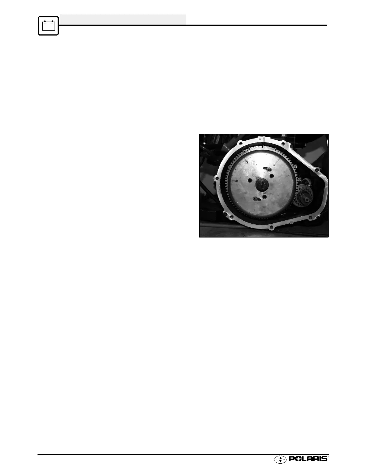
Ignition Timing Adjustment
1. Remove flywheel cover.
2. Loosen magnet holder screws.
3. Rotate magnet holder to adjust ignition timing.
Rotating the magnet holder clockwise (as viewed
from the front) will advance the timing and rotating
counterclockwise will retard timing. Move the
magnet holder in the opposite direction
approximately the same amount as the mark must
move. Tighten screws securely.
4. Verify proper ignition timing with the timing light.
Static Ignition Timing Adjustment
Static Timing Light tool (PN 2871745) can used to verify that the hall effect sensors are working.
1. To check the sensors, simply connect the white test wire to the Green, Red, or Blue (1200s only) wires from
the stator. The light should come on and go out sharply (as indicated in static timing) if the sensor is
functioning properly. If the light glows faintly or is slow to react, the Hall Effect sensor is damaged.
 Loading...