4 - 34
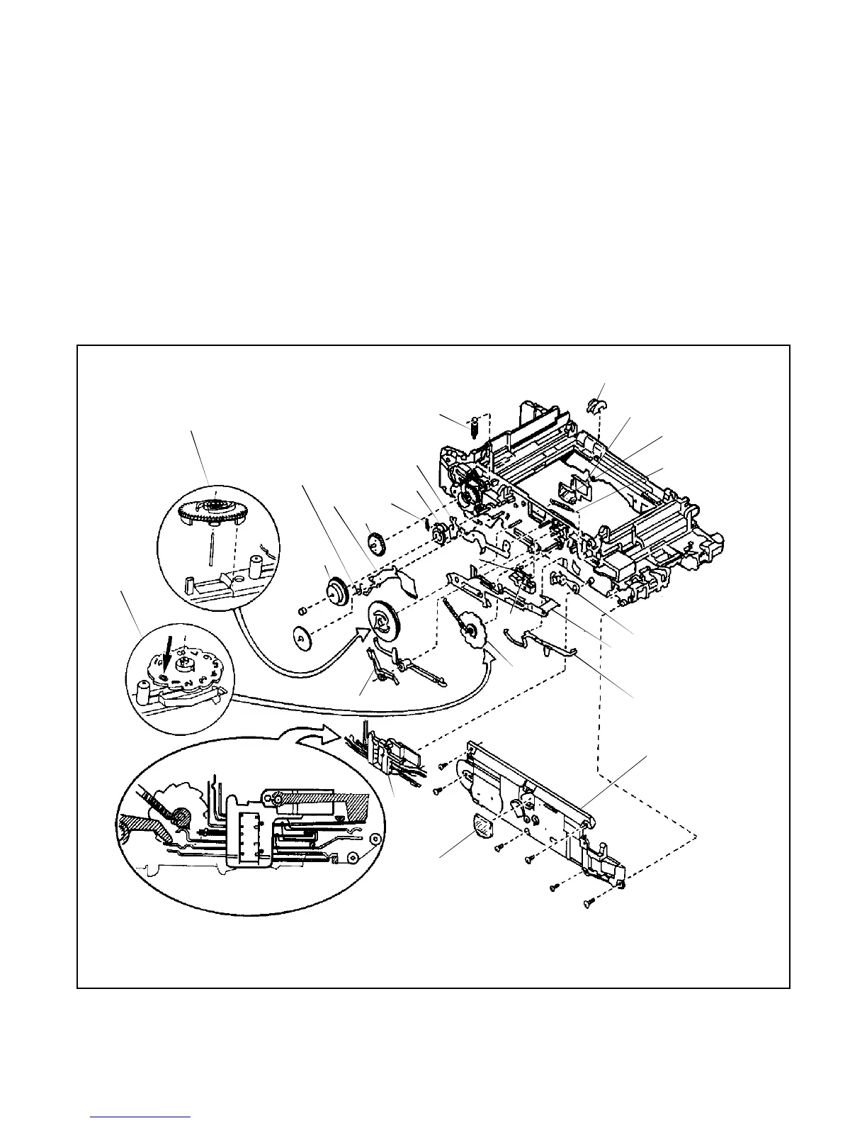
2. Reassembly
To reassemble the Gear Side -Outer of the Main Frame of the camera, follow the disassembly steps
in reverse order.
Note: When reassembling Gear Side -Outer of the Main Frame of the camera make sure:
• Contacts of 5-Wire Detail Switch are properly positioned. (See nsert in Figure 4-42 for
location of contacts.)
• Zero (0) position of the Counter wheel must be aligned with the screw post on the Main
Frame of the camera.
• Cam of the Timing Gear must initially sit behind the metal Pick tab.
Figure 4-42. Disassembly of Main Frame (Gear Side - Outer)
1
2
4
5
7
6
8
9
10
11
12
3
14
15
16
17
18
13
19
20
21
22
TIMING
GEAR
COUNTER
WHEEL
MIRROR
CATCHER
OUTER
VF LENS
DRIVE
COVER
 Loading...