• Use Input 5 and Output 2. Input 5 is not echo cancelled by the video codec and Output 2 is a mix of
all inputs to the codec except for Input 5. If Input 5 or Output 2 is not available, use Input 6 and
Output 3. Input 6 is also is not echo cancelled by the video codec and Output 3 is a mix of all inputs
to the codec except for Input 6.
• Make sure that the Input/Output combination you decide to use is enabled. Go to A
UDIO SETTINGS,
I
NPUTS and make sure that the ON box is enabled for that Input. Perform the same task for AUDIO
SETTINGS, OUTPUT.
• Disable the AGC on Input 5 or Input 6 (depending on which Input is connected to the Vortex device).
Once that is completed, make sure that the Input to the Vortex device is assigned to the appropriate AEC
Reference signal. Consult the Reference Manual for the Vortex device or the Help file in Conference
Composer for more information.
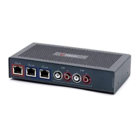
WIRING FROM CODEC TO VORTEX DEVICE
The inputs and outputs to most codecs are unbalanced. We recommend keeping the cable
from the Vortex device as short as possible to avoid any common-mode signals that may
corrupt the audio.
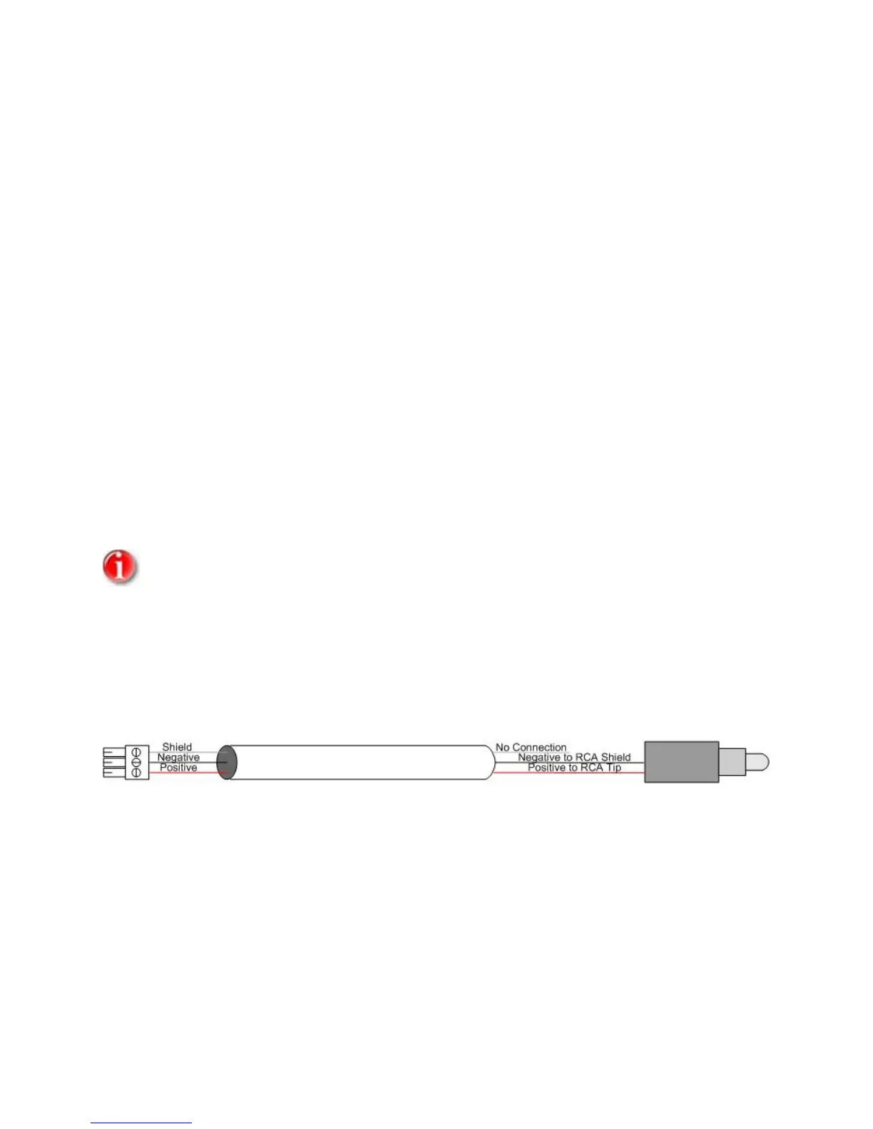
INPUT TO CODEC FROM OUTPUT OF VORTEX DEVICE
Connect the Positive conductor of the Vortex device to the Tip of the RCA connector and the Negative
conductor of the Vortex device to Shield of the RCA connector.
The shield of the cable is not connected.
66