User manual Pomac PLP Lobe pump
12 CE/PLP (1406) EN-12
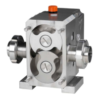
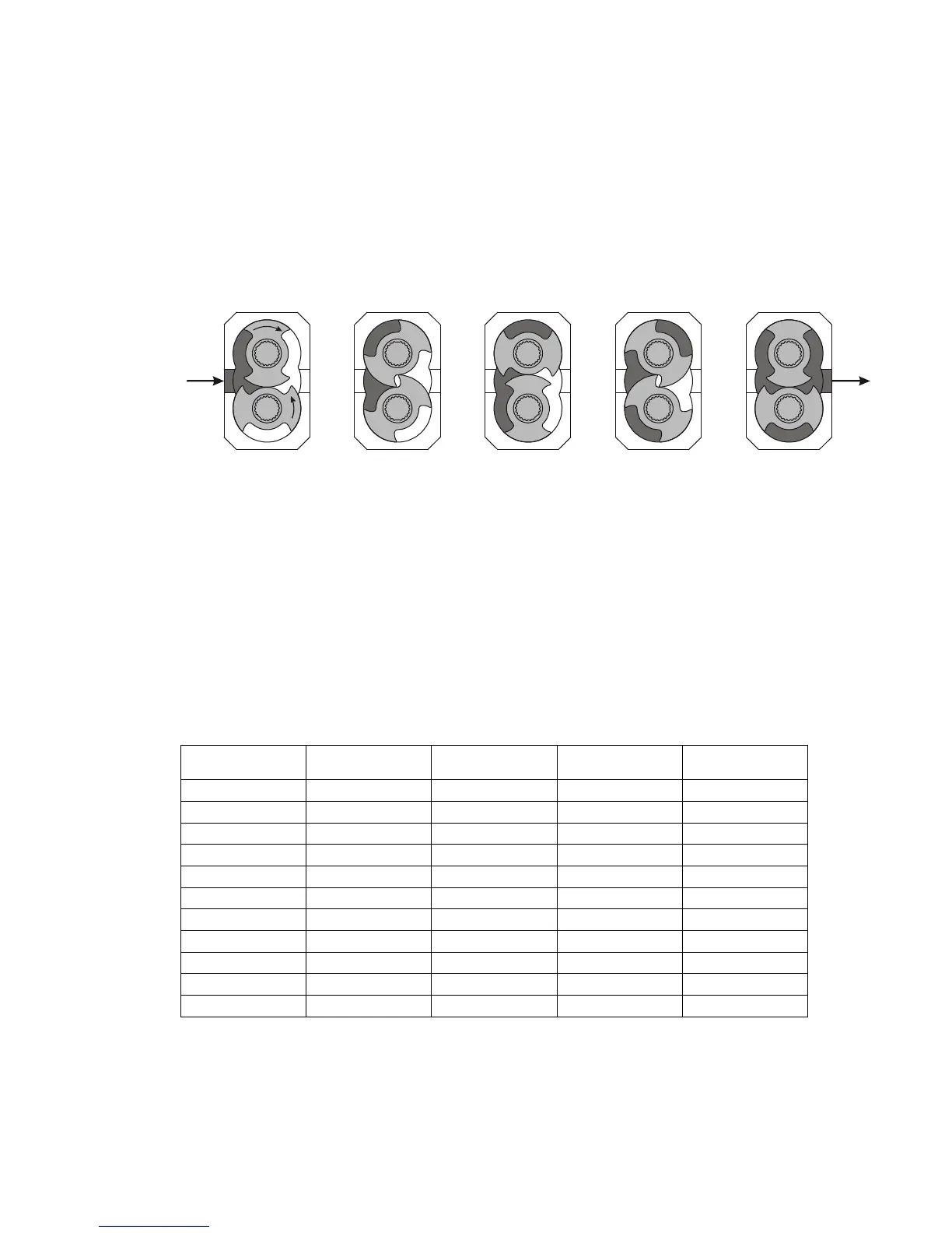
3.2. Operating principle
A lobe pump is a rotary positive displacement pump. The operating principle is based on the
counter-rotation of 2 rotors in a chamber. Both rotors are mounted on shafts. The shafts are
supported by bearing cartridges, which are directly mounted to the pump casing. One of the
shafts is externally driven. An internal gear transmission drives the other shaft in opposite
direction. The rotors run synchronously in the opposite directions, without touching each other.
When the rotors pass the suction port the volume between the rotors increases. This creates a
pressure decrease which causes the liquid to flow into the suction port. During rotation a fixed
amount of liquid is conveyed.
When the rotors approach the pressure port the volume between the rotors decreases. This
creates a pressure increase which causes the liquid to flow out of the pressure port.
3.3. Delivery program
Connections
The delivery program comprises pump types with connections of ¾”, 1”, 1 ½”, 2", 2 ½”, 3" and
4".
The pump can be placed with its connections either horizontally or vertically.
Shaft seals
The following shaft seal variants are available:
⚫ Single mechanical seal
⚫ Double mechanical seal, quenched or flushed
⚫ O-ring seal
⚫ Double O-ring seal, quenched
⚫ Lip seal.
3.4. Application area
*) Dependent on the gap between rotor and pump casing.
The values mentioned above are maximum values. The operational values may be lower
because of the liquid characteristics or the system design.